6
7
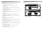
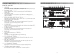
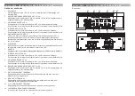
CONNE CONTROLS EA-M4 AND EA-M4
x
1 RCA INPUTS
Low-level RCA signal input CH1/2/3/4 for connection to head-unit.
2 INPUT GAIN CONTROL 1/2-CH
Input gain potentiometer for channel 1/2-CH, to match the output voltage of the head-
unit to the amplifier’s input.
3 HIGHPASS FREQUENCY CONTROL 1/2-CH
Switch set to “ON” activates the highpass control potentiometer to adjust the
crossover highpass filtering frequency point of the amplifier.
4 LOWPASS FREQUENCY CONTROL 1/2-CH
Switch set to “ON” activates the lowpass control potentiometer to adjust the crossover
lowpass filtering frequency point of the amplifier.
5 INPUT CHANNEL MODE
In case you only have one stereo RCA cable, switch set to “2-CH”, connect the RCA
cable to the CH1/2 RCA input sockets and the amplifiers internally routes the signal to
CH3/4. If you connect four RCA cables, set the switch to “4-CH”.
6 POWER LED
LED to show proper operating status of the amplifier by white illumination. Protect
state of amplifier is signaled by the red LED.
7 REMOTE CONTROL
Port for the optional available remote control.
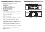
8 LOWPASS FREQUENCY CONTROL 3/4-CH
Switch set to “ON” activates the lowpass control potentiometer to adjust the crossover
lowpass filtering frequency point of the amplifier.
9 HIGHPASS FREQUENCY CONTROL 3/4-CH
Switch set to “ON” activates the highpass control potentiometer to adjust the
crossover highpass filtering frequency point of the amplifier.
10 INPUT GAIN CONTROL 3/4-CH
Input gain potentiometer for channel 3/4-CH, to match the output voltage of the head-
unit to the amplifier’s input.
11 “GND” POWER INPUT TERMINAL
Terminal to connect the amplifier to the chassis ground or negative pole of the car
battery.
12 “REM” INPUT TERMINAL
Terminal to connect the amplifier to the automatic (remote) turn-on / turn-off lead of the
head unit.
13 “+12V” POWER INPUT TERMINAL
Terminal to connect the amplifier to the po12V pole of the car battery.
14 SPEAKER OUTPUT TERMINAL
Output terminal to connect the speakers to the amplifier in either stereo or bridged
mode.
4
5 6
8
7
1
2
3
EA-M4
x
bm bn bo
bp
bl
9
Side panels
CONNE CONTROLS EA-M4 AND EA-M4
x
Summary of Contents for EA-M1
Page 13: ...Rev A...


