8
the head-unit's low-pass frequency setting is not lower than the frequency set-
ting ("FREQ. Hz") on your amplifier. In case your head-unit does not have a
separate subwoofer signal output, you will have to 'split' the stereo input
signal by means of a Y-adaptor cable, so that you will have two connectors
for each channel available: one for LPF (using "REAR" section of the ampli-
fier) and one for HPF (using "FRONT" section).
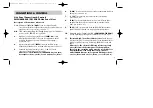
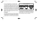
2.3. Stereo, Bridged-Mono or Tri-Mode Amplification
Stereo Connection:
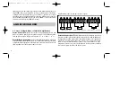
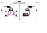
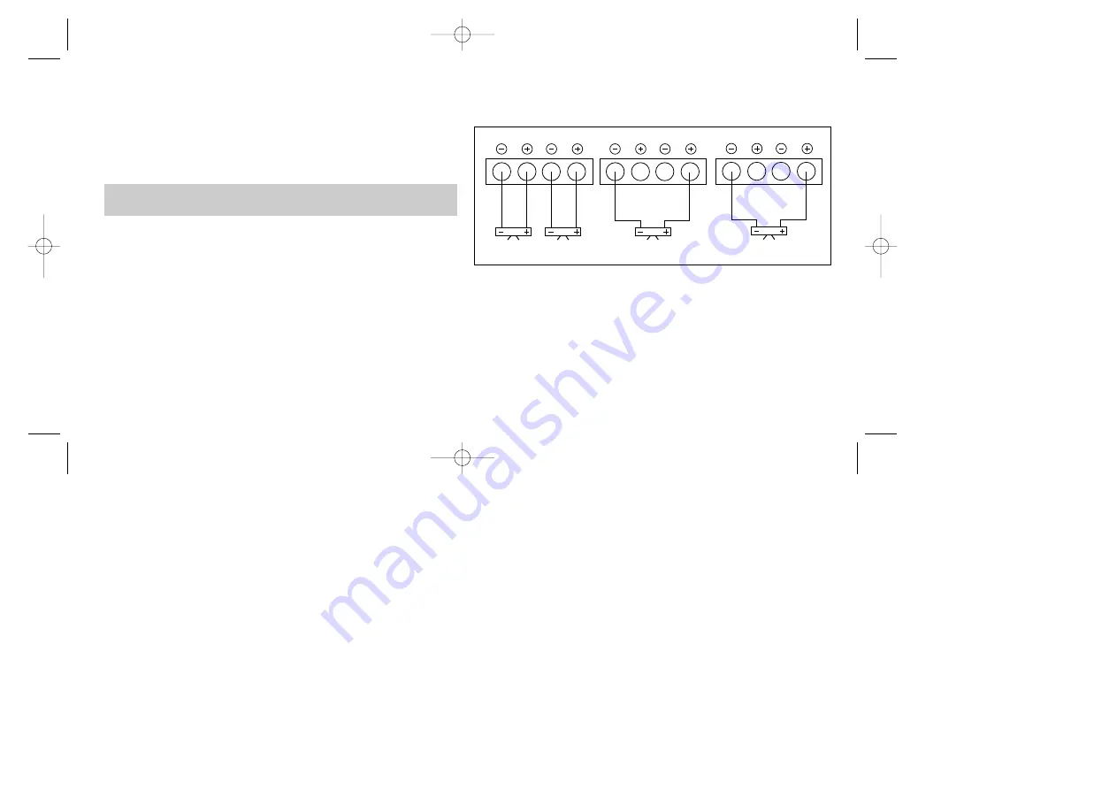
please refer to the connecting diagrams below and
make sure, that the polarity of your speaker wiring is correct all the way down
from amplifier output to the speaker terminals:
to
and
to
.
Mono-Bridged Connection:
In mono (bridged) mode, please refer to the
respective connecting diagram. The mono-mode will provide approximate-
ly triple the rated output power of a single stereo channel. In mono-mode, the
load impedance must be kept at or above 2 ohms!
Amplification Modes (for any pair of stereo outputs)
Tri-Mode Connection:
This amplification mode describes the connection
of a stereo speaker pair as in the regular stereo mode but with an additional,
third speaker (usually a subwoofer) connected to the same set of speaker ter-
minals. For correct tri-mode connection, please refer to the respective dia-
gram. For best results with tri-mode systems it is recommended to use a spe-
cial passive tri-mode cross-over. The impedance of each speaker combined
in a tri-mode system should not be below 4 ohms.
AMPLIFICATION MODES
R
L
STEREO CONNECTION
R
L
BRIDGED MONO CONNECTION
R
L
BRIDGED MONO CONNECTION
EA2190490 Manual neu 31.07.2000 19:02 Uhr Seite 8

