background image

12431-10-1008

Page 12

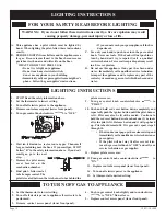
1.   STOP! Read the safety information above. 
2.  Set the thermostat to lowest setting.
3.  Turn off all electric power to the appliance.
4.   Remove control access panel (lower front panel).
5.   Turn gas control knob clockwise 

 to "OFF."


6.   Wait ten (10) minutes   to clear out any gas.  Then smell 

for gas, including near the floor.  If you smell gas, STOP! 

Follow "B" in the safety information above.  If you don't 

smell  gas,  go  to  the  next 

step.

7.   Remove  the  pilot  access 

cover  located  on  the 

combustion chamber.  

8.   Find pilot - follow metal 

tube from gas control.  The 

pilot is located between the two burner tubes behind the 

pilot access cover.

9.   Turn  gas  control  knob  counterclockwise 

  to 

"PILOT."

10.  Push  and  hold  red  reset  button  down  completely  and 

repeatedly push the ignitor button until the pilot burner 

is lit.  Pilot may also be lit with a match.  Continue to 

hold the red reset button down for about one (1)   minute 

after the pilot is lit.  Release button and it will pop back 

up.  Pilot should remain lit.  If it goes out, repeat steps 5 

through 10.

•  If button does not pop up when released, stop and 

immediately call a qualified service technician or 

gas supplier.   

•  If  the  pilot  will  not  stay  lit  after  several  tries, 

turn the gas control knob to "OFF" and call your 

service technician or gas supplier.  

11.  Replace pilot access cover.

12. Turn gas control knob counterclockwise 

    to 

"ON."

13.   Replace control access panel (lower front panel).
14.   Turn on all electric power to the appliance.

15.   Set thermostat to desired setting.

FOR YOUR SAFETY READ BEFORE LIGHTING

WARNING:  If you do not follow these instructions exactly, a fire or explosion may result 

causing property damage, personal injury or loss of life.

A.   This  appliance  has  a  pilot  which  must  be  lighted  by 

hand.  When lighting the pilot, follow these instructions 

exactly.

B.   BEFORE LIGHTING  smell all around the appliance area 

for gas.  Be sure to smell next to the floor because some 

gas is heavier than air and will settle on the floor.


WHAT TO DO IF YOU SMELL GAS

• Do not try to light any appliance.

• Do not touch any electrical switch; 

  do not use any phone in your building.

• Immediately call your gas supplier from a neighbor's 

phone.  Follow the gas supplier's instructions.

• If you cannot reach your gas supplier, call the fire 

department.

C.   Use only your hand to push in or turn the gas control 

knob.  Never use tools.  If the knob will not push in or 

turn by hand, don't try to repair it; call  a  qualified 

service technician.  Force or attempted repair may result 

in a fire or explosion.

D.   Do not use this appliance if any part has been under 

water.  Immediately call a qualified service technician 

to inspect the appliance and to replace any part of the 

control system and any gas control which has been under 

water.

TO TURN OFF GAS TO APPLIANCE

1.   Set the thermostat to lowest setting.
2.   Turn off all electric power to appliance if service is to be 

performed .

3.   Remove  control  access panel  (lower front panel).

4.   Push in gas control  knob slightly and turn clockwise 

  to "OFF." Do not force.

5.   Replace control  access panel  (lower front panel).

LIGHTING INSTRUCTIONS

LIGHTING INSTRUCTIONS

Summary of Contents for DV-55SPP

Page 1: ...se death or serious illness Installer Leave this manual with the appli ance Consumer Retain this manual for future refer ence Do not store or use gasoline or other amma ble vapors and liquids in the v...

Page 2: ...tts 5 Introduction 6 Speci cations 6 Gas Supply 7 8 Clearances 8 Installation Instructions 9 11 Lighting Instructions 12 Pilot Flame Characteristics 13 Main Burner Flame Characteristics 13 Wiring 14 S...

Page 3: ...appliance should be inspected before use and at least annually by a quali ed service person More frequent cleaning may be required due to excessive lint from carpeting bedding materials etc It is imp...

Page 4: ...ghts perform service or make adjustments in an area where the conditions are such that you may not detect the odor if there has been a leak of LP Gas Odor fade due to oxidation by rust or adsorption o...

Page 5: ...iredinaccordance with the above provisions shall comply with NFPA 720 and be ANSI UL 2034 listed and IAS certi ed 3 SIGNAGE Ametalorplasticidenti cationplateshallbe permanently mounted to the exterior...

Page 6: ...e by a moving vehicle Quali ed Installing Agency Installation and replacement of gas piping gas utilization equip ment or accessories and repair and servicing of equipment shall be performed only by a...

Page 7: ...e disconnected from piping at inlet of control valve and pipe capped or plugged for pressure test Never pressure test with appliance connected control valve will sustain damage A gas valve and ground...

Page 8: ...istance from the center of the vent cap to the nearest outside corner or obstruction is 24 inches The vent terminal of a direct vent appliance with an input over 50 000 BTU per hour shall be located a...

Page 9: ...0 x 1 screws provided Side outlet kit 10 boot assembly with register SOK 1 for warm air discharge into an adjoining room may be installed on either side of the furnace at the required clearance of 4 i...

Page 10: ...e mountingplate Useadditionalcaulkingtocorrectunevenwall surface such as clapboard 2 Remove old furnace cement from ue outlet collar on com bustion chamber and collar of vent cap Remove old furnace ce...

Page 11: ...it appears that a projection within 6 of any side of the air inlet section could shield the air inlet section the entire vent should be supported away from the wall at least the distance of the projec...

Page 12: ...ectric power to the appliance 15 Set thermostat to desired setting FOR YOUR SAFETY READ BEFORE LIGHTING WARNING If you do not follow these instructions exactly a re or explosion may result causing pro...

Page 13: ...ing the burner door from the combustion chamber remove rear burner pilot burner and front burner With front and rear burners removed from furnace force water into the ribbon ports and dry with air pr...

Page 14: ...ing can be purchased plugged into the ungrounded receptacle and its wire connected to the receptacle mounting screw With this wire completing the ground the appliance cord plug can bepluggedintotheada...

Page 15: ...rnace is rst installed or was off all summer the pilot ame may be too lean to ignite on the rst few trials Turn the controlvalveknobtopilotpositionanddepresstheredresetbutton Holding the button down c...

Page 16: ...Gasket for Burner Door 40 722040 Manifold Union 41 R 5655 Gas Valve VR8200C LP Gas 41 R 2148 Gas Valve VR8200C Natural Gas 42 UH 810 Transformer Mounting Bracket 43 R 1995 Transformer 44 UH 451 Juncti...

Page 17: ...12431 10 1008 Page 17 PARTS VIEW...

Page 18: ...12431 10 1008 Page 18 SERVICE NOTES...

Page 19: ...12431 10 1008 Page 19 SERVICE NOTES...

Page 20: ...ms Empire Comfort Systems Inc 918 Freeburg Ave Belleville IL 62220 If you have a general question about our products please e mail us at info empirecomfort com If you have a service or repair question...

Reviews: