background image

12431-10-1008

Page 16

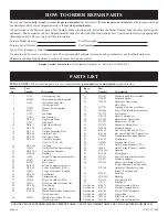
PLEASE NOTE:  

When ordering parts, it is very important that  

part number

 and 

description

 of part coincide.

Index 

Part

 No. 

Number 

Description

  USE ONLY MANUFACTURER'S REPLACEMENT PARTS.  USE OF ANY OTHER PARTS COULD CAUSE INJURY OR DEATH.

  1 

11762 

Outer Casing Top

  2 

632024 

Motor Mount (Four Required)

  3 

11764 

Motor Mounting Bar 


(Two Required)

  4 

712059 

Gasket (Two Required)

  5 

R-619 

Motor

  6 

11787 

Fan Blade

  7 

11766 

Fan Housing 

  8 

DV-559 

Upper Front Panel 

  9 

11759 

Side Panel 

  10 

DV-613 

Right Inner Shield

  11 

DV-725 

Vent Cap 

  12 

DV-131 

Outside Mounting Plate

  13 

DV-548 

Air Inlet Tube

  14 

DV-524 

Flue Outlet Tube

  15 

DV-600 

Vent Kit Complete 


(Nos. 11, 12, 13, 14)

  16 

DV-1386 

Air Drop 

  17 

712036 

Gasket for Flue Outlet Flange

  18 

DV-579-C 

Combustion Chamber 

  19 

8720130 

Bushing

  20 

11765 

Switch Compartment Assembly

  21 

912073 

Limit Control

  22 

R-1941 

Fan Control

  23 

DV-832 

Switch Compartment Cover

  24 

DV-562 

Lower Front Panel (USA)

  24 

15667 

Lower Front Panel (Canada)

  25 

DV-826 

Rear Burner 

  26 

672046 

Thermocouple

  27 

762214 

Pilot with Orifice LP Gas

  27 

762111 

Pilot with Orifice Natural Gas

  28 

DV-808 

Pilot Tubing

  29 

DV-824 

Front Burner 

  30 

P-88-42 

Main Burner Orifice Natural Gas


(Two Required)

  30 

742223 

Main Burner Orifice LP Gas 


(Two Required)   

Index 

Part

  No. 

Number 

Description

  31 

DV-687 

Manifold and Plate Assembly

  32 

712045 

Manifold Gasket

  33 

712098 

Gasket for Observation 


Hole Cover

  34 

DV-781 

Lighting Hole Cover w/Mica

  35 

DV-064 

Cover Plate for Observation Hole

  36 

DV-775 

Seal Bracket

  37 

712059 

Gasket Tubing Seal

  38 

DV-622 

Burner Door Natural Gas

  38 

DV-973 

Burner Door LP Gas

  39 

DV-779 

Gasket for Burner Door

  40 

722040 

Manifold Union

  41 

R-5655 

Gas Valve VR8200C LP Gas

  41 

R-2148 

Gas Valve VR8200C Natural Gas

  42 

UH-810 

Transformer Mounting Bracket

  43 

R-1995 

Transformer

  44 

UH-451 

Junction Box Cover 

  45 

11760 

Outer Casing Bottom (USA)

  45 

15690 

Outer Casing Bottom (Canada) 

  46 

8720148 

Bushing

  47 

R-2708 

Piezo Ignitor

  48 

DV-571 

Control Compartment Divider

  49 

DV-671 

Manifold Support

  50 

DV-765 

Gasket  for Chamber Air Inlet 


(Top & Bottom) (Two Required)

  51 

DV-764 

Gasket for Chamber Air Inlet


(Sides) (Two Required)

  52 

872053 

Cord Set

  53 

8720140 

Bushing

  54 

DV-614 

Left Inner Shield

  55 

11759 

Side Panel

 Not Shown 

R-9832 

Wiring Assembly Upper

Not Shown 

R-9833 

Wiring Assembly Lower

Not Shown 

R-6389 

24 Volt Wall Thermostat

Not Shown 

862060 

Lighter Rod

Not Shown 

742265 

Pilot Orifice LP Gas

Not Shown 

742159 

Pilot Orifice Natural Gas

Parts can be ordered

 only

 through your 

service person or dealer.

 For best results, the 

service person or dealer

 should order parts through 

the distributor. Parts can be shipped directly to the 

service person/dealer

.

All parts listed in the Parts List have a Part Number. When ordering parts, first obtain the Model Number from the name plate on your 

equipment. Then determine the Part Number (

not

 the Index Number) and the Description of each part from the following appropriate 

illustration and list. Be sure to give all this information.
Furnace Model Number 

    Part Description 

Furnace Serial Number  

  Part Number 

Type of Gas (Propane or Natural) 
Do not order bolts, screws, washers or nuts. They are standard hardware items and can be purchased at any local hardware store. 
Shipments contingent upon strikes, fires and all causes beyond our control.

Empire Comfort Systems, Inc.  

Nine Eighteen Freeburg Ave.   Belleville, IL  62220-2623

HOW TO ORDER REPAIR PARTS

PARTS LIST

Summary of Contents for DV-55SPP

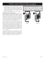
Page 1: ...se death or serious illness Installer Leave this manual with the appli ance Consumer Retain this manual for future refer ence Do not store or use gasoline or other amma ble vapors and liquids in the v...

Page 2: ...tts 5 Introduction 6 Speci cations 6 Gas Supply 7 8 Clearances 8 Installation Instructions 9 11 Lighting Instructions 12 Pilot Flame Characteristics 13 Main Burner Flame Characteristics 13 Wiring 14 S...

Page 3: ...appliance should be inspected before use and at least annually by a quali ed service person More frequent cleaning may be required due to excessive lint from carpeting bedding materials etc It is imp...

Page 4: ...ghts perform service or make adjustments in an area where the conditions are such that you may not detect the odor if there has been a leak of LP Gas Odor fade due to oxidation by rust or adsorption o...

Page 5: ...iredinaccordance with the above provisions shall comply with NFPA 720 and be ANSI UL 2034 listed and IAS certi ed 3 SIGNAGE Ametalorplasticidenti cationplateshallbe permanently mounted to the exterior...

Page 6: ...e by a moving vehicle Quali ed Installing Agency Installation and replacement of gas piping gas utilization equip ment or accessories and repair and servicing of equipment shall be performed only by a...

Page 7: ...e disconnected from piping at inlet of control valve and pipe capped or plugged for pressure test Never pressure test with appliance connected control valve will sustain damage A gas valve and ground...

Page 8: ...istance from the center of the vent cap to the nearest outside corner or obstruction is 24 inches The vent terminal of a direct vent appliance with an input over 50 000 BTU per hour shall be located a...

Page 9: ...0 x 1 screws provided Side outlet kit 10 boot assembly with register SOK 1 for warm air discharge into an adjoining room may be installed on either side of the furnace at the required clearance of 4 i...

Page 10: ...e mountingplate Useadditionalcaulkingtocorrectunevenwall surface such as clapboard 2 Remove old furnace cement from ue outlet collar on com bustion chamber and collar of vent cap Remove old furnace ce...

Page 11: ...it appears that a projection within 6 of any side of the air inlet section could shield the air inlet section the entire vent should be supported away from the wall at least the distance of the projec...

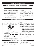
Page 12: ...ectric power to the appliance 15 Set thermostat to desired setting FOR YOUR SAFETY READ BEFORE LIGHTING WARNING If you do not follow these instructions exactly a re or explosion may result causing pro...

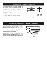
Page 13: ...ing the burner door from the combustion chamber remove rear burner pilot burner and front burner With front and rear burners removed from furnace force water into the ribbon ports and dry with air pr...

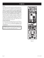
Page 14: ...ing can be purchased plugged into the ungrounded receptacle and its wire connected to the receptacle mounting screw With this wire completing the ground the appliance cord plug can bepluggedintotheada...

Page 15: ...rnace is rst installed or was off all summer the pilot ame may be too lean to ignite on the rst few trials Turn the controlvalveknobtopilotpositionanddepresstheredresetbutton Holding the button down c...

Page 16: ...Gasket for Burner Door 40 722040 Manifold Union 41 R 5655 Gas Valve VR8200C LP Gas 41 R 2148 Gas Valve VR8200C Natural Gas 42 UH 810 Transformer Mounting Bracket 43 R 1995 Transformer 44 UH 451 Juncti...

Page 17: ...12431 10 1008 Page 17 PARTS VIEW...

Page 18: ...12431 10 1008 Page 18 SERVICE NOTES...

Page 19: ...12431 10 1008 Page 19 SERVICE NOTES...

Page 20: ...ms Empire Comfort Systems Inc 918 Freeburg Ave Belleville IL 62220 If you have a general question about our products please e mail us at info empirecomfort com If you have a service or repair question...

Reviews: