background image

Page 10

32188-0-0616

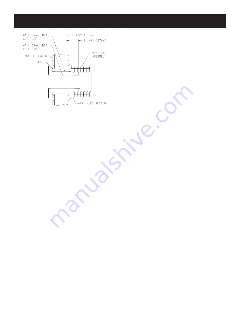
Cutting Vent Tubes

This is the most important part of the installation. With the furnace 

installed on wall the 6" diameter air inlet tube and the 4" diameter flue 

outlet tube are to be marked and cut using the following procedure.

1.  attach 6" diameter air inlet tube onto the collar of air drop as-

sembly. Be sure 6" diameter air inlet tube is placed as far as 

possible onto the collar of the air drop assembly. Mark the 6" 

diameter air inlet tube 1/2" beyond the outside wall. Remove 

6" diameter air inlet tube from collar of air drop assembly.

2.  Attach 4" diameter flue outlet tube onto flue outlet collar on 

combustion chamber. Be sure 4" diameter flue outlet tube is 

placed as far as possible onto the collar of flue outlet. Mark 

the 4" diameter flue outlet tube 2 1/4" beyond the outside wall. 

Remove 4" diameter flue outlet tube from collar of flue outlet 

on combustion chamber.

3.  Mark or wrap tape completely around the tubes at the marked 

points to help in making a true cut. Do not crimp or enlarge 

tubes.

Installing Vent Assembly

1.  Place caulking (not provided) beneath the edge of the outside 

mounting plate. Use additional caulking to correct uneven wall 

surface, such as clapboard.

2.  attach 6" diameter air inlet tube onto the collar of air drop 

assembly. Attach caulked, outside mounting plate into the 6" 

diameter air inlet tube. Position the outside mounting plate so 

that 6" diameter air inlet tube has a slight downward slope to the 

outside. 

The downward slope is necessary to prevent the 

entry of rainwater.

 attach outside mounting plate to exterior 

wall with (4) #10 x 1 1/2" screws provided.

3.  Apply furnace cement to 4" diameter flue outlet collar on com

-

bustion chamber and to 4" diameter collar on vent cap. attach 

4" diameter flue outlet tube onto flue outlet collar on combustion 

chamber. Attach vent cap into the 4" diameter flue outlet tube. 

Attach vent cap to outside mounting plate with (3) #10 x 1/2" 

screws provided.

4.  Installation is completed.

Reassembly And Resealing Vent-Air Intake System

When vent-air intake system is removed for servicing the furnace, 

the following steps will assure proper reassembly and resealing of 

the vent-air intake assembly.
1.  Remove old caulking beneath the edge of the outside mount

-

ing plate. Apply new caulking beneath the edge of the outside 

mounting plate. Use additional caulking to correct uneven wall 

surface, such as clapboard.

2.  Remove old furnace cement from flue outlet collar on combustion 

chamber and collar of vent cap. Remove old furnace cement 

from both ends of 4" diameter flue outlet tube.

3.  attach 6" diameter air inlet tube onto the collar of air drop 

assembly. Attach caulked, outside mounting plate into the 6" 

diameter air inlet tube. Position the outside mounting plate so 

that 6" diameter air inlet tube has a slight downward slope to the 

outside. 

The downward slope is necessary to prevent the 

entry of rainwater.

 attach outside mounting plate to exterior 

wall with (4) #10 x 1" screws provided.

4.  Apply furnace cement to 4" diameter flue outlet collar on com

-

bustion chamber and to 4" diameter collar on vent cap. attach 

4" diameter flue outlet tube onto flue outlet collar on combustion 

chamber. Attach vent cap into the 4" diameter flue outlet tube. 

Attach vent cap to outside mounting plate with (3) #10 x 1/2" 

screws provided.

5.  Reassembly and resealing vent-air intake system is completed.

Figure 8

Locating Electric Supply

A 7/8" diameter knockout is provided at the bottom of the left and 

right side panels. A three-prong (grounding) plug assembly is located 

within  the  control  compartment  (bottom)  of  the  furnace.  Please 

remove 7/8" knockout from appropriate side panel when routing 

plug assembly to an electrical outlet.

Installation of Three-prong (Grounding) Plug Assembly

1.  Disconnect nylon cap on 3' plug assembly from nylon plug on 

wiring harness. Remove 3' plug assembly from control compart

-

ment (bottom) of the furnace.

2.  Remove 7/8" knockout from appropriate side panel.

3.  Insert nylon cap on 3' plug assembly into the 7/8" hole in the side 

panel.

4.  Connect nylon cap on 3' plug assembly to nylon plug on the 

wiring harness.

5.  Place 7/8" strain relief bushing around the cord of the 3' plug 

assembly. Insert 7/8" strain relief bushing into the 7/8" hole in 

the side panel.

Attention! 

The 7/8" strain relief bushing is located within the same 

envelope as the Installation Instructions and Owner's Manual.

Attaching Furnace to Wall

Refer to Figure 5 for the location of the 7 1/2" diameter wall open

-

ing for the furnace. after the wall opening has been located and 

cut, position flue outlet on furnace in center of wall opening. When 

attaching furnace to the wall remove that portion of baseboard and 

molding on the wall which is behind the furnace. attach furnace to 

wall, at the outer casing top, with (2) toggle bolts provided and to floor, 

at the outer casing bottom, with (2) #10 x 1 1/2" screws provided.

Attention!

 The screw holes on the outer casing bottom are off-set 

above the floor approximately 3/8". Do not over-tighten screws and 

distort the off-set on the outer casing bottom. Distortion of the outer 

casing bottom will not allow the lower front panel to be attached 

to the furnace.

INSTALLATION INSTRUCTIONS (continued)

Summary of Contents for DVC55SPPXLP-1

Page 1: ...combustion which can cause death or serious illness Installer Leave this manual with the appliance Consumer Retain this manual for future reference WARNING If the information in these instructions ar...

Page 2: ...duction 6 Specifications 6 Gas Supply 7 8 Clearances 8 Installation Instructions 9 11 Lighting Instructions 12 Pilot Flame Characteristics 13 Main Burner Flame Characteristics 13 Wiring 14 Service and...

Page 3: ...The appliance should be inspected before use and at least annually by a qualified service person More frequent cleaning may be required due to excessive lint from carpet ing bedding materials etc It i...

Page 4: ...gas can adsorb or absorb onto or into walls masonry and other materials and fabrics in a room That will take some of the odorant out of the gas reducing its odor intensity LP Gas may stratify in a clo...

Page 5: ...oxide detector as required in accordance with the above provisions shall comply with NFPA 720 and be ANSI UL 2034 listed and IAS certified 3 SIGNAGE A metal or plastic identification plate shall be pe...

Page 6: ...ied Installing Agency Installation and replacement of gas piping gas utilization equip ment or accessories and repair and servicing of equipment shall be performed only by a qualified agency The term...

Page 7: ...local authorized installer for installation or relocation Compounds used on threaded joints of gas piping shall be resistant to the action of liquefied petroleum gases The gas lines must be checked f...

Page 8: ...distance from the center of the vent cap to the nearest outside corner or obstruction is 24 inches CLEARANCES Checking Manifold Pressure Both Propane and Natural gas valves have a built in pressure re...

Page 9: ...provided Side outlet kit 10 boot assembly with register SOK 1 for warm air discharge into an adjoining room may be installed on either side of the furnace at the required clearance of 4 inches to adj...

Page 10: ...ove old furnace cement from both ends of 4 diameter flue outlet tube 3 Attach 6 diameter air inlet tube onto the collar of air drop assembly Attach caulked outside mounting plate into the 6 diameter a...

Page 11: ...e projection 2 x 4 framing whose outside dimensions match the overall dimensions of the mounting plate is recommended The 2 x 4 framing protects siding from possible warpage or discoloration All joint...

Page 12: ...power to the appliance FOR YOUR SAFETY READ BEFORE LIGHTING Warning If you do not follow these instructions exactly a fire or explosion may result causing property damage personal injury or loss of l...

Page 13: ...emovingthe burner door from the combustion chamber remove rear burner pilot burner and front burner With front and rear burners removed from furnace force water into the ribbon ports and dry with air...

Page 14: ...toggle switch or thermostat remove the wire nut from the two wires from the valve Run additional wire from the valve wires to the ON OFF device Install the ON OFF device in the same room as the furnac...

Page 15: ...r Does Not Light Pilot With air in the gas line such as when the furnace is first installed or was off all summer the pilot flame may be too lean to ignite on the first few trials Turn the control val...

Page 16: ...l Gas 28 DV808 Pilot Tubing 29 DV824 Front Burner 30 P8842 Main Burner Orifice Natural Gas Two Required 30 P8853 Main Burner Orifice LP Gas Two Required 31 DV687 Manifold and Plate Assembly 32 M148 Ma...

Page 17: ...Page 17 32188 0 0616 PARTS VIEW...

Page 18: ...ranty parts All parts listed in the Parts List have a Part Number When ordering parts first obtain the Model Number and Serial Number from the name plate on your equipment Then determine the Part Numb...

Page 19: ...le cancelled check or payment record should be kept to verify purchase date and establish warranty period Ready access to the appliance for service What Is Not Covered Damages that might result from t...

Page 20: ...mfort Systems Empire Comfort Systems Inc Belleville IL If you have a general question about our products please e mail us at info empirecomfort com If you have a service or repair question please cont...

Page 21: ...rieuses maladies Ne pas entreposer ni utiliser d essence ni d autres vapeurs ou liquides inflammables dans le voisnage de cet appareil ou de tout autre appareil QUE FAIRE SI VOUS SENTEZ UNE ODEUR DE...

Page 22: ...st chaud lorsque le radiateur est en fonction L installation et la r paration doivent tre faites par une per sonne qualifi e L appareil doit tre inspect avant l usage et au moins une fois par ann e pa...

Page 23: ...bas Attendez que les pompiers vous assurent de la s ret de ces endroits avant d y aller Utiliser le t l phone de votre voisin et appeler les pompiers et une personne entra n e avec le propane Ne pas...

Page 24: ...e gaz d entrer par le capuchon de l vent Emplacement de l Ouverture dans le Mur Le radiateur doit tre situ sur un mur ext rieur Trouver les montants du mur ainsi l ouverture dans le mur sera entre les...

Page 25: ...d espace libre aux mat riaux combus tibles venant du d gage ment du registre de chaque c t Entr e de gaz Enlever plinthe et moulure ouverture d vent 7 1 2 19cm Mur ar ri re Minimum d espace libre au c...

Page 26: ...l entr e de la pluie Attacher la plaque ext rieure de montage au mur ext rieur avec 4 vis 10 x 1 38mm Les vis sont fournies 4 Appliquer du ciment pour radiateur au collet de la sortie Emplacement de l...

Page 27: ...ourrev tementnedoitpasexc derune paisseur totale de 13 33 02cm pour le DV 55 voir Figure 5a AVERTISSEMENT Lorsque l ensemble d vent pour le rev tementenvinyleDV 822oulaconstructionfaitede2 x 4 5 08cm...

Page 28: ...x et de raccords en m tal ondul ANS Z21 45 Connexions flexibles d appareil autre qu en m tal Les connexions ci dessus peuvent tre utilis es si elles sont accept es par les autorit s ayant juridiction...

Page 29: ...index no 4 pi ce no 712059 Les joints d tanch it doivent tre tir s pour s adapter sur les boulons du moteur dans les espaces pour joint d tanch it Le moteur et les joints d tanch it peuvent tre insta...

Page 30: ...tournerle bouton de contr le de gaz N utiliserjamais des outils Si vousnepouvezpaspousseroutournerleboutonavecvos mains n essayerpasdeler parer appeleruntechnicien qualifi Forcer ou essayer de r parer...

Page 31: ...a veilleuse et r allumer La veilleuse s enflamme mais s teint lorsque le bouton est rel ch 1 Suivre les instructions et appuyer sur le bouton plus long temps et fermement 2 D terminer si la flamme de...

Page 32: ...semblage du br leur avant 30 P8842 Br leur principal avec ouverture gaz naturel exige deux 30 P8853 Br leur principal avec ouverture gaz propane exige deux 31 DV687 Tuyau de gaz et assemblage de plaqu...

Page 33: ...Page 13 32188 0 0616 Empire Comfort Systems Inc Nine Eighteen Freeburg Ave Belleville Illinois 62220 2623...

Page 34: ...aiement pour attester de la date d achat et tablir la p riode de garantie Acc s imm diat l appareil pour la r paration Ce qui n est pas couvert Dommages pouvant r sulter de l emploi de l emploi abusif...

Page 35: ...Page 15 32188 0 0616 NOTES DE SERVICE...

Page 36: ...ire Comfort Systems Inc Belleville IL Pour toute question g n rale concernant nos produits veuillez nous envoyer un courriel info empirecomfort com Pour toute question d entretien ou de r paration veu...

Reviews: