30784-2-1112
Page 61
RF OPERATING INSTRUCTIONS
RF VALVE OPERATION (AF-4040 Electronic Gas Valve system
only)
Please refer to the separate instructions for detailed operation and
programming of the Multi-function Remote Control.
The AF-4040 Electronic Gas Control Valve features a Remote con-
trolled High/Low Variable - 6 Volt DC Motor Drive. This gas control
uses a spark to pilot burner assembly. For use with Propane or
natural gas (pre-set at the factory).
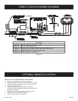
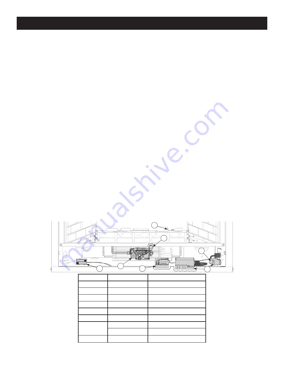
This gas control system includes the items identified in Figure 75.
SPECIAL FEATURES ON THE CONTROL MODULE
The Control Module has two special pilot mode features built into
the system.
CONTINUOUS PILOT FEATURE:
This allows the user to change
from a spark to pilot system to a standing pilot system.
1. There is a switch located on the right side of the Control
Module (#4) that reads CONTINUOUS PILOT ON/OFF. This
switch will allow the user to select the pilot mode of opera-
tion.
2. When the continuous pilot switch is in the OFF position and
the appliance turned ON, the pilot will spark and light, then the
main burner will light as well. When the appliance is turned
OFF, the pilot and main burner will shut OFF.
3. When the continuous pilot switch is in the ON position and
the appliance is turned ON, the pilot will spark and light. Then
when the appliance is turned OFF the pilot will remain ON,
but the main burner will shut OFF.
Note: The Continuous pilot mode setting is generally recom-
mended on Direct Vent appliances during cold climate sea-
sons to help keep the firebox warm.
REMOTE CONTROL FEATURE:
The Control Module has a built
in remote control receiver which allows the user to program the
hand held remote transmitter.
1. There is a switch located on the right side of the Control Mod-
ule that reads REMOTE/OFF.
2. When the remote/off switch is in the OFF position the appli-
ance will operate from an appliance mounted rocker switch
(#3) or optional wall switch connected to the two (2) BROWN
wires on the Control Module.
3. When the remote/off switch is in the REMOTE position the
appliance will operate from the Remote Control transmitter.
The Control Module must be programmed to the Remote Control.
1. To program, located the learn button on the left side of the
Control Module Note: Press and release the learn button.
There will be a beep sound from the Control Module, then
press any key on the remote transmitter. Once the internal
receiver accepts the transmitter code there will be a series of
confirming beeps.
2. To switch between the NG and LP step motor settings, press
and hold the learn button for 20 seconds. The module should
emit a short beep (less than 1 second) to indicate that the
control was switched from NG (default setting) to LP. When
switching back from LP to NG, the control should emit a long
beep (3 seconds).
POWER SUPPLY SYSTEM
The Gas Control system is powered by a standard 110 volt AC
through a 6.0 volt DC adaptor. The AC adaptor is connected to the
Control Module with two 1/4” female terminals.
This control system also includes a Battery Back-up pack that al-
lows the Gas Control system only to operate in the event of a
power outage.
NOTE:
The Accent Light and/or Blower features will not operate
during a power outage.
NOTE:
All Batteries should be replaced at least once each year,
preferably at the beginning of the heating season.
CAUTION:
Fire or explosion hazard. Can cause property damage,
sever injury or death.
Do not attempt to take apart the gas control or to clean it. Improper
assembly and cleaning can cause unreliable operation.
Index No.
Part No.
Description
1
R10418
Battery Back-up
2
R10415
AF Valve, RF
3
R2522
Off/On Switch
4
R11007
AF Control Module
5
R10416
AF Extension Module
6
R10419
AC Adapter
7
R10423
Pilot Assembly - Nat
R10424
Pilot Assembly - LP
Not Shown
R11006
Remote Control, RF
1
2
3
4
5
6
7
Figure 75


