background image


START UP/OPERATION INSTRUCTIONS 

 
WIRING 
Prior to electrical hookup please refer to Wiring Schematic on next page. 
 
CLEANING 


Remove the factory applied rust inhibitor with a degreasing agent or oil soaked rags. 
 

LUBRICATION 


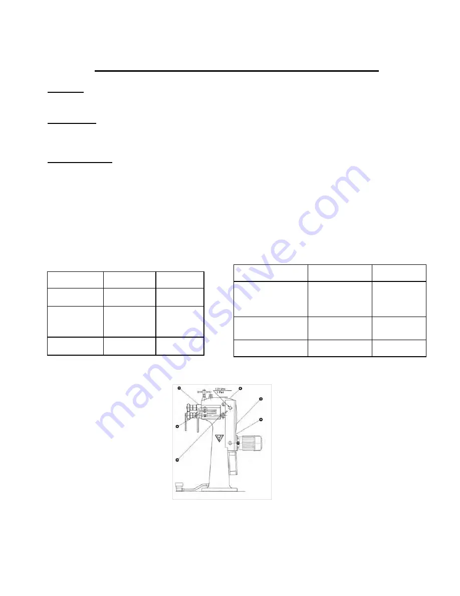
Check gearbox Oil Sight Glass (2) for proper oil levels  
The following tables will provide you with manufacturers and types of oil and grease recommended by 
the factory. 
 
Lubricate all points as marked with the proper grease using the fitting included in this information 
package. 


US GREASE & OIL SPECIFICATIONS                  CANADIAN GREASE & OIL SPECIFICATIONS


BRAND


GREASE


OIL


 US Mobil Brand


Mobilux Grease 

2


Mobil DTE 24

Shell OilUS 

Product Info#1-

800-231-6950


Alvania 

EP2Alvania 

Gerase 2


Shell Tellus 32

 Esso


Lonax/Lidok 

EP2


Nuto H32


BRAND


GREASE


OIL


Nemco Available in: 

Winnipeg, Regina, 

Saskatoon


LCEP2


Hydrol AW32


Shell Canada


Alvania EP2Alvania 

Grease 2


Shell Tellus 32

Esso


Lonax/Lidok EP2


Nuto H32


Summary of Contents for EMT-7R

Page 1: ...hinery com Web www empire machinery com Imported By Instruction Parts Manual for EMT 7R Power Rotary Machine Operator must read and understand Instruction Manual prior to operating the EMT 7R Power Rotary Machine as damage to machine or personal injury may result Electrician must refer to electrical schematics in this manual before initial startup ...

Page 2: ...If any of these EMT 7R safety labels are missing from the machine or damaged it is the owner s responsibility to contact Empire Machinery Tools Ltd immediately for replacement labels ...

Page 3: ...st read and understand the Operators Manual Never operate machine with any guards removed Do not use machine if service is required Use safety glasses and required protective equipment Keep work areas clean and in proper order It is the responsibility of the owner of this machine and shop supervisor to ensure that all operators of this machine are properly trained on the safe operation of this mac...

Page 4: ... grease recommended by the factory Lubricate all points as marked with the proper grease using the fitting included in this information package US GREASE OIL SPECIFICATIONS CANADIAN GREASE OIL SPECIFICATIONS BRAND GREASE OIL US Mobil Brand Mobilux Grease 2 Mobil DTE 24 Shell OilUS Product Info 1 800 231 6950 Alvania EP2Alvania Gerase 2 Shell Tellus 32 Esso Lonax Lidok EP2 Nuto H32 BRAND GREASE OIL...

Page 5: ...r locations near the back of the shafts DEPTH CONTROL The EMT 7R comes standard with a manual screw adjustment for control of the upper shaft depth 9 If you look directly behind the Adjusting Screw you will see the Upper Shaft Tensioning Screw 10 This is factory set and should never need adjustment ROLL INSTALLATION Rolls must be secured by means of the Roll Locking Nuts 5 provided Upper Roll Lock...

Page 6: ......

Page 7: ...EMT 7R Parts Breakdown ...

Page 8: ......

Page 9: ......

Page 10: ......

Page 11: ......

Page 12: ...olls 1 2 20 Smooth Flanging Rolls 20Ga Heavier 1 2 20 KNURLED Flanging Rolls better on lighter gauges Wiring specify 1 16 1 8 3 16 1 4 5 16 Closing Slitting Rolls Spin In Collar Rolls 22GA lighter Base Raises working height from 31 1 2 42 Optional Electrics 440V 3PH Air Cylinder Package c w Depth Stop Raises Lower Top Shaft with Foot Switch Not to Be Used with 20 Flange Rolls or Spin In Rolls Air ...

Page 13: ...ght from 33 to 38 Optional Speed Control gives operator infinitely variable speed and forward reverse at the flip of a switch High Efficiency Motor Dual Voltage Motor Safety Covered Footswitch 11 Throat Depth Bead 1 8 3 16 1 4 3 8 1 2 Offset Slit Crimp or Combination Bead Crimp 1 4 or 1 2 90 Flange Rolls Pipe Stays in Horizontal Position ...

Page 14: ...aft and adjust the bottom roll until there is about 2 times material thickness between the male and female portion of the rolls Adjust the backstop up to the back of the bottom roll so it is almost touching the roll but not rubbing and lock in place Place material onto the bottom roll and up against the backstop Start the rolls turning and bring the top shaft down and form the offset You may be re...

Page 15: ...op Bring the top roll down until the top and bottom roll just about touch Adjust the threaded collar on the bottom shaft until there is about 2 times the material thickness spacing Tighten the locking collars Bring the backstop up to the shoulder on the bottom roll just so it does not rub on the roll The capacity on the rolls is 14 Ga To 22 Ga If you are using lighter gauge material ie 22 Ga you m...

Page 16: ... down until the rolls mesh together Tighten the locking collars Adjust the backstop up to the end of the crimp rolls and tighten When you are ready to form the crimp With the rolls separated place your material over the bottom roll until the material is against the backstop DO NOT START THE MACHINE UNTIL YOU BRING THE TOP ROLL DOWN AND TIGHTEN FIRMLY TOGETHER SANDWICHING THE MATERIAL BETWEEN THE R...

Page 17: ...ith the highest portion of the roll facing out Bring the top shaft down until the rolls mesh together Tighten the locking collars Adjust the backstop up to the end of the crimp rolls and tighten When you are ready to form the crimp With the rolls separated place your material over the bottom roll until the material is against the backstop DO NOT START THE MACHINE UNTIL YOU BRING THE TOP ROLL DOWN ...

Page 18: ...ction operations To adjust the air cylinder to the desired depth use your thumb and adjust the Knurled Nut which is located inside the window of the yellow finger guard Screwing the Knurled Nut down will shorten the stroke of the cylinder and lessen the depth of the profile being formed Raising the Knurled Nut will allow the rolls to come closer together thereby allowing the profile to be deeper I...

Page 19: ...ONTROL Each part may vary and must be programmed with this in mind Some parts require a full revolution before the top shaft can be fed down i e Spin In Collar and Flange Rolls With this in mind you will need to vary your speed of the rolls to match the settings on the control This can only be done with a little bit of trial and error There are three different settings that make up a program and t...

Page 20: ...ake you into a different screen there will be three different settings that can be changed on this screen and they are explained as follows RISE TIME This value is the time that the control allows for the top shaft to rise after the program is finished or the HOME button is pushed WAIT TIME This value is the wait time allowed after the top shaft reaches the top of stroke This value is important as...

Page 21: ... will stop it movement and hold in that position To continue stepping down the top shaft you can lightly tap your foot to the floor and bring it back to the center position until the desired depth for your profile is achieved Once your part is finished raise your foot completely off the foot pedal and the top shaft will return to its home position and the rolls will stop rotating For repetitive pa...

Page 22: ...Electrical Schematics for Air Oil Hydraulic Package EMPIRE EMT 7R PIPE FORMER ...

Page 23: ...UNIVERSAL EMT 7 ...

Page 24: ...UNIVERSAL EMT 7 ...

Page 25: ...UNIVERSAL EMT 7 ...

Page 26: ...UNIVERSAL EMT 7 ...

Page 27: ......

Page 28: ......

Page 29: ...Instruction Manual Maximum Operating Pressure 10 000 PSI 7 0 8 0 v e r 0 M 0 0 6 A P This is the safety alert symbol It is used to alert you to potential personal injury hazards Obey all safety messages that follow this symbol to avoid possible injury or death ...

Page 30: ...ls PA1500 Components PA1500 shown Reservoir Manifold Plug Oil Output Port Plastic Cap Air Input Port Foot Pedal NOT USED ON EMT 7R Shipping Air Vent Plug replace Shipping Plug with Air Vent Plug prior to use PRODUCT DESCRIPTION BVA Hydraulics Air Hydraulic Pumps are engineered to meet most Industrial Standards for Performance and Safety Its unique hydraulic circuit allows quick displacement of hyd...

Page 31: ...oses Do not subject the pump and its components to shock loads Use only approved accessories and approved hydraulic fluid Never attach ANY component not authorized by manufacturer Always ensure that the chosen application is stable to work on and around Do not connect to application which can return more oil to the reservoir than the pump reservoir can hold Do not connect pump to hydraulic system ...

Page 32: ...nt 4 For Models PA1500 1 To extend the cylinder depress on the foot pedal until desired position is reached 2 To hold the cylinder in position release the foot pedal to the half way detent to deactivate the pump 3 To retract the cylinder release foot pedal Note Never operate a pump which is disconnected from application If operate in this condition the hose and connections will become pressurized ...

Page 33: ...medy overload condition Contact Service Center Replace application connection Application responds slower than normal Loose connection or coupler Restricted hydraulic line or fitting Application connection leaking Tighten connection or coupler Clean and replace if damaged Replace application connection Application does not return fluid to pump i e cylinder will not retract Malfunctioning coupler d...

Page 34: ...00 M0 rev 08 07 Air Hydraulic Pump Service Parts Note Not all components of the pump are replacement items but are illustrated as a convenient reference of location and position in the assembly sequence Parts Illustration ...

Page 35: ...or piston 1 35 A57 3 1011 108 Pump piston 1 36 512 2 0410 017 Compression spring 1 37 A57 6 1014 102 Pump piston guide 1 38 A57 6 2023 108 Bushing 1 Item PA1500 Part Description Qty 39 573 7 0120 105 Back up ring 1 40 U cup 1 41 A59 6 1013 105 Pump piston cylinder 1 42 A57 6 1016 106 Spacer 1 43 H18 6 8103 104 Crush washer 1 44 A57 6 1001 204 Base hydraulic unit 1 45 A57 6 1605 105 Gasket 1 46 511...

Page 36: ...raulics product fails due to material defect in workmanship you may contact SFA for disposition In such cases the customer s sole and exclusive remedy for any breach or alleged breach of warranty is limited to the repair or replacement of the defective product Under no circumstances is BVA Hydraulics liable for any consequential or incidental damage or loss whatsoever THIS WARRANTY IS LIMITED TO N...

Page 37: ......

Page 38: ...Instruction Manual Maximum Operating Pressure 10 000 PSI 7 0 8 0 v e r 0 M 0 0 6 A P This is the safety alert symbol It is used to alert you to potential personal injury hazards Obey all safety messages that follow this symbol to avoid possible injury or death ...

Page 39: ...els PA1500 Components PA1500 shown Reservoir Manifold Plug Oil Output Port Plastic Cap Air Input Port Foot Pedal NOTUSED ONEMT 7R Shipping Air Vent Plug replace Shipping Plug with Air Vent Plug prior to use PRODUCT DESCRIPTION BVA Hydraulics Air Hydraulic Pumps are engineered to meet most Industrial Standards for Performance and Safety Its unique hydraulic circuit allows quick displacement of hydr...

Page 40: ...oses Do not subject the pump and its components to shock loads Use only approved accessories and approved hydraulic fluid Never attach ANY component not authorized by manufacturer Always ensure that the chosen application is stable to work on and around Do not connect to application which can return more oil to the reservoir than the pump reservoir can hold Do not connect pump to hydraulic system ...

Page 41: ...nt 4 For Models PA1500 1 To extend the cylinder depress on the foot pedal until desired position is reached 2 To hold the cylinder in position release the foot pedal to the half way detent to deactivate the pump 3 To retract the cylinder release foot pedal Note Never operate a pump which is disconnected from application If operate in this condition the hose and connections will become pressurized ...

Page 42: ...medy overload condition Contact Service Center Replace application connection Application responds slower than normal Loose connection or coupler Restricted hydraulic line or fitting Application connection leaking Tighten connection or coupler Clean and replace if damaged Replace application connection Application does not return fluid to pump i e cylinder will not retract Malfunctioning coupler d...

Page 43: ...00 M0 rev 08 07 Air Hydraulic Pump Service Parts Note Not all components of the pump are replacement items but are illustrated as a convenient reference of location and position in the assembly sequence Parts Illustration ...

Page 44: ...or piston 1 35 A57 3 1011 108 Pump piston 1 36 512 2 0410 017 Compression spring 1 37 A57 6 1014 102 Pump piston guide 1 38 A57 6 2023 108 Bushing 1 Item PA1500 Part Description Qty 39 573 7 0120 105 Back up ring 1 40 U cup 1 41 A59 6 1013 105 Pump piston cylinder 1 42 A57 6 1016 106 Spacer 1 43 H18 6 8103 104 Crush washer 1 44 A57 6 1001 204 Base hydraulic unit 1 45 A57 6 1605 105 Gasket 1 46 511...

Page 45: ...raulics product fails due to material defect in workmanship you may contact SFA for disposition In such cases the customer s sole and exclusive remedy for any breach or alleged breach of warranty is limited to the repair or replacement of the defective product Under no circumstances is BVA Hydraulics liable for any consequential or incidental damage or loss whatsoever THIS WARRANTY IS LIMITED TO N...

Page 46: ......

Reviews: