background image

27440-1-0510

Page 12

notice  (damper clamp Installation)

When installing your log set as a vented installation the damper 

clamp must be used.

When installing your log set as a vent-free installation the damper 

clamp can be used to eliminate the potential for odors when burning 

the logs for the first time.

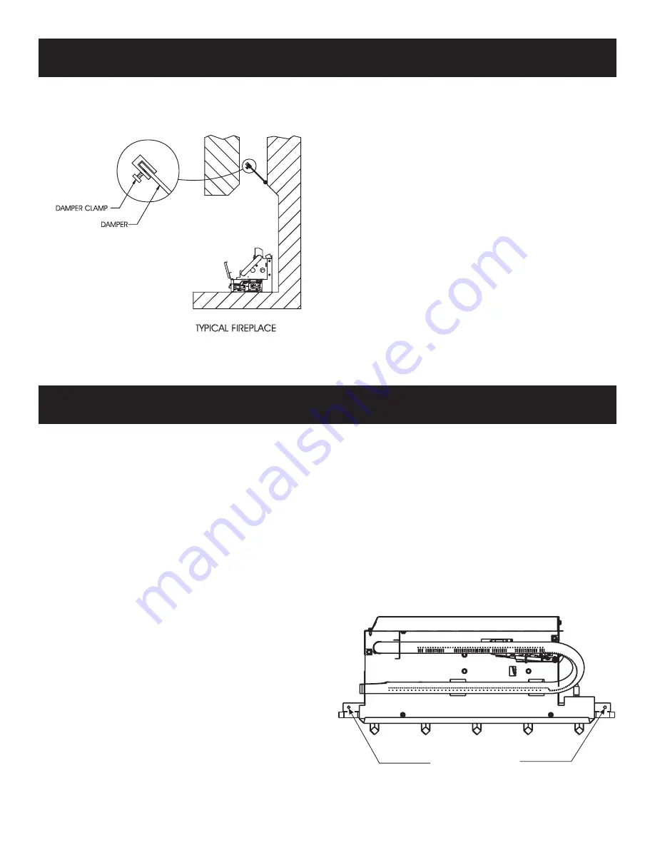
Installing damper clamp (figure 9) 

Remove all ashes or other debris from the fireplace. If the fireplace 

is equipped with an ash dump be sure to seal the door with furnace 

cement or high temperature silicone. Be sure to check the damper 

for proper operation and verify that the flue passageway is open.

Place the clamp over the lip of the damper and tighten the hold 

down bolt until the clamp is securely attached to the damper. This 

will prevent the damper from accidentally closing. 
Manual and millivolt controlled gas logs may be installed as a 

vented decorative log set in compliance with ANSI Z21.60 and 

National Fuel Gas Code. When the gas logs are operated with the 

damper  open,  non-combustible  material  and  minimum  mantel 

requirements do not apply.

•  Turn off the gas supply to the fireplace or firebox.

•  Seal any fresh air vents and/or ash clean-out doors located on 

the floor or wall of the fireplace. If left unsealed, drafting may 

cause pilot outage or sooting. Use a heat resistant sealant. Do 

not seal the chimney flue damper.

Before installing in a solid fuel burning fireplace, the chimney flue 

and firebox must be cleaned of soot, creosote, ashes and loose paint 

by a qualified chimney cleaner.

you must secure the gas log heater to the fireplace floor. If 

not, the entire unit may move when you adjust the controls. 

Movement of unit may cause shifting of the gas logs which 

leads to sooting and improper burning. Grate movement 

could cause a gas leak.
Special care is required if you are installing the unit into a 

sunken fireplace. you must raise the fireplace floor to allow 

access to gas log controls. This will insure adequate air flow 

and guard against sooting. Raise the fireplace floor using 

noncombustible materials.

assembly Procedure: (figure 10)

1. Center the gas log unit in the fireplace or firebox. Make certain 

the front feet of the grate sit inside the front edge of the fireplace 

or firebox.

2. An anchor hole is provided in the two bottom side members of 

the grate frame. After centering the grate correctly, mark the 

hole positions on the fireplace/firebox floor. Drill two (2) 5/32" 

diameter holes approximately 1-1/2" deep for masonry screws 

or 1/8" hole for sheet metal screws.

3. Anchor the grate to the fireplace/firebox floor using the screws 

provided. Refer to Figure 10. 

Proper installation of the grate is essential to prevent any move

-

ment of the gas logs and controls during operation.

figure 10

figure 9

ANCHOR SCREW

LOCATIONS

InSTaLLInG aS a VenTed aPPLIance

BefoRe fuLLy InSTaLLInG THe aPPLIance

Summary of Contents for VFDM18LBWN-1

Page 1: ...e vicinity of this or any other appliance WHAT TO DO IF YOU SMELL GAS Do not try to light any appliance Do not touch any electrical switch do not use any phone in your building Immediately call your gas supplier from a neighbor s phone Follow the gas supplier s instructions If you cannot reach your gas supplier call the fire department Installation and service must be performed by a qualified inst...

Page 2: ...0 VFDR18LBW10 Log Placement 14 Operation Instructions Flame Appearance 15 Wiring VFDR Models Only 16 VFDR 18 24 30 LBW Lighting Instructions 17 VFDR18LBW10 N P Lighting Instructions 18 VFDT 18 24 30 LBW Lighting Instructions 19 VFDM 18 24 30 LBW Lighting Instructions 20 Pilot Flame Characteristics 21 22 Cleaning and Servicing 22 Troubleshooting 23 VFDR Series Parts List 24 VFDR Series Parts View 2...

Page 3: ...only allow operation of this appliance in a vented configuration Check your state or local codes Correct installation of logs properlocation of the heaterand annual cleaning are necessary to avoid potential problems with sooting Sooting resulting from improper installation or operation can settle on surfaces outside the fireplace Avoid any drafts that could alter burner flame patterns Do not allow...

Page 4: ...ghts perform service or make adjustments in an area where the conditions are such that you may not detect the odor if there has been a leak of LP Gas Odor fade due to oxidation by rust or adsorption on walls of new cylinders and tanks is possible Therefore people should be particularly alert and careful when new tanks or cylinders are placed in service Odor fade can occur in new tanks or reinstall...

Page 5: ...nce 3 Installer should show owner how to start and operate unvented room heater vented decorative appliance Always consult your local Building Department regarding regulations codes or ordinances which apply to the installation of an unvented room heater vented decorative appliance This appliance may be installed in an aftermarket manufactured mobile home where not prohibited by state or local cod...

Page 6: ...Regulator Pressure Setting Gas Inlet Pressure Max Gas Inlet Pressure Minimum VFDR 18 24 30 LBW Natural Millivolt 3 5 W C 10 5 W C 4 5 W C Propane 10 0 W C 13 0 W C 11 0 W C VFDR18LBW10 Natural Millivolt 3 5 W C 10 5 W C 5 0 W C Propane 10 0 W C 13 0 W C 11 0 W C VFDT 18 24 30 LBW Natural Thermostat 6 0 W C 10 5 W C 7 0 W C Propane 10 0 W C 13 0 W C 11 0 W C VFDM 18 24 30 LBW Natural Manual 6 0 W C...

Page 7: ...0 x 1 2 black sheet metal anchoring screws Ceramic Log Set 5 Piece on VFDR 18 24 VFDT 18 24 and VFDM 18 24 7 Piece on VFDR30 VFDT30 and VFDM30 Plastic bag containing glowing embers rock wool for burner coverage The millivolt controlled heater may be operated with optional devices for REMOTE OFF ON functions a Wall switch or thermostat with wire b Hand held remote control with ON OFF switch or ther...

Page 8: ...supplied for use with the log set 6 Also refer to IMPORTANT SAFETY INFORMATION on page 3 of this manual WARNING DO NOT OPERATE THIS GAS LOG SET WITH GLASS DOORS CLOSED Clothing or other flammable material should not be placed on or near the appliance Do not place trash or other articles on the log set during op eration During manufacturing fabricating and shipping various components of this applia...

Page 9: ...onal Fuel Gas Code defines a confined space as a space whose volume is less than 50 cubic feet per 1 000 Btu per hour 4 8m3 per kw of the aggregate input rating of all appliances installed in that space and an unconfined space as a space whose volume is not less than 50 cubic feet per 1 000 Btu per hour 4 8 m3 per kw of the aggregate input rating of all appliances installed in that space Rooms com...

Page 10: ...for 18 24 and 30 logs from the fireplace opening Mantel Clearances Without Hood Figure 4 You must have non combustible materials above the fireplace opening Non combustible material must extend at least 12 above fireplace opening With sheet metal you must have non combustible material behind it Heat resistant materials such as slate and marble must be at least 1 2 thick Sheet metal should not be i...

Page 11: ... factory built fireplaces Free opening area of chimney damper for venting combustion products from decora tiveappliancesforinstallationinsolidfuel burning fireplaces Height is from hearth to top of chimney and the minimum height is 10 feet Chart shows minimum opening sq in for given height and input rate Do not attach combustible material to the mantel of your fireplace This is a fire hazard Figur...

Page 12: ...al the chimney flue damper Before installing in a solid fuel burning fireplace the chimney flue and firebox must be cleaned of soot creosote ashes and loose paint by a qualified chimney cleaner You must secure the gas log heater to the fireplace floor If not the entire unit may move when you adjust the controls Movement of unit may cause shifting of the gas logs which leads to sooting and improper...

Page 13: ...ped on the bottom in which condensation and foreign particles may collect Figure 11 The use of the following gas connectors is recommended ANSZ21 24ApplianceConnectorsofCorrugatedMetalTubing and Fittings ANS Z21 45 Assembled Flexible Appliance Connectors of Other Than All Metal Construction The above connectors may be used if acceptable by the authority havingjurisdiction ThestateofMassachusettsre...

Page 14: ...ER MATERIAL PLACEMENT ON BURNER 7 After all logs are positioned properly apply Rockwool ember material to the front burner port area To apply carefully separate the ember material into small amounts no larger than dime size pieces Fluffed up pieces one layer thick on top of the burner generally works best and will provide the best ember glow Do not place ember material more than one layer thick No...

Page 15: ...g smoke and smells as they are burned off during the initial operation of the appliance possibly causing headaches or eye or lung irritation This is a normal and temporary occurrence The initial break in operation should last 2 3 hours with the burner at the highest setting Provide maximum ventilation by opening windows or doors to allow odors to dissipate Any odors remaining after this initial br...

Page 16: ...riod you can release the gas control knob and the pilot will stay ON Allow your pilot flame to operate an additional one 1 to two 2 minutes before you turn the gas control knob from the PILOT position to the ON position This time period allows the millivolts electrical current to buildup to a sufficient level allowing the gas control to operate properly Millivolt Control The valve regulator contro...

Page 17: ... 4 Turn off all electric power to the appliance if applicable 5 Push in gas control knob slightly and turn clockwise to OFF NOTE Knob cannot be turned from PILOT to OFF unless knob is pushed in slightly Do not force 6 Wait ten 10 minutes to clear out any gas Then smell for gas including near the floor If you smell gas STOP Follow B in the safety information above If you do not smell gas go to the ...

Page 18: ...ver assembly if applicable 3 Set REMOTE OFF ON switch to OFF 4 Turn off all electric power to the appliance if applicable 5 Push in gas control knob slightly and turn clockwise to OFF NOTE Knob cannot be turned from PILOT to OFF unless knob is pushed in slightly Do not force 6 Wait ten 10 minutes to clear out any gas Then smell for gas including near the floor If you smell gas STOP Follow B in the...

Page 19: ...fety information above If you do not smell gas go to the next step 6 Find pilot the pilot is located in front of the rear log 7 Turn manual gas control knob coun terclockwise to PILOT 8 Push in manual gas control knob all the way and hold in Repeatedly push the piezo ignitor button until pilot is lit or use a match to light Continue to hold the control knob in for about one 1 minute after the pilo...

Page 20: ...lear out any gas Then smell for gas including near the floor If you smell gas STOP Follow B in the safety information above If you do not smell gas go to the next step 4 Find pilot the pilot is located in front of the rear log 5 Turn manual gas control knob counterclockwise to PILOT 6 Push in manual gas control knob all the way and hold in Repeatedly push the piezo ignitor button until pilot is li...

Page 21: ...ouching the thermocouple This will cause the thermocouple to cool When the thermocouple cools the heater will shut down Correct Pilot Flame Pattern for VFDR Figure 20 Correct Pilot Flame Pattern for VFDT VFDM Figure 21 Incorrect Pilot Flame Pattern for VFDR Figure 22 Incorrect Flame Pattern for VFDT VFDM Figure 23 If pilot flame pattern is incorrect as shown in Figures 22 and 23 See Troubleshootin...

Page 22: ... clean will result in sooting and poor combustion ANNUALCLEANING INSPECTION Referto parts diagram for location of items discussed below Inspect and clean burner air intake hole Remove lint or particles with vacuum or brush Failure to keep air intake hole clean will result in sooting and poor combustion Inspect and clean all burner ports Inspect ODS pilot for operation and accumulation of lint at a...

Page 23: ...ed f Gas regulator setting is not correct Replace gas regulator 7 ODS pilot lights but flame goes out when control knob is released a Control knob not fully pressed in Press in control knob fully b Control knob not pressed in long enough After ODS pilot lights keep control knob pressed in 30 seconds c Manual Shutoff valve not fully open Fully open manual shutoff valve d Thermocouple connection loo...

Page 24: ...561 21561 21561 TUBING ASSEMBLY VALVE TO PILOT LPG 12 21559 21559 21559 TUBING ASSEMBLY REGULATOR TO PILOT NAT 13 R7063 R7063 R7063 REGULATOR NAT PILOT 14 21560 21560 21560 TUBING ASSEMBLY VALVE TO REGULATOR NAT ONLY 15 21562 21563 21564 TUBING ASSEMBLY 16 R2423 R2423 R2423 CONNECTOR MALE 17 21589 21589 21589 VALVE BRACKET 2 REQUIRED 18 R3626 R3626 R3626 VALVE NAT 18 R3625 R3625 R3625 VALVE LPG 19...

Page 25: ...OG SET 32 27 30 28 29 31 30 BURNER 1 2 3 4 5 6 7 8 9 10 11 12 14 13 17 18 19 20 23 24 15 16 21 22 25 26 1 2 3 4 5 6 7 8 9 10 11 12 14 13 17 18 19 20 23 24 18 BURNER 15 16 21 22 25 26 24 BURNER 1 2 3 4 5 6 7 8 9 10 11 12 14 15 16 13 17 18 19 20 21 24 25 26 ...

Page 26: ... R7572 JAMB NUT 8 21669 BURNER BASE SUB ASSEMBLY 9 21581 LEG REAR 2 REQUIRED 10 P214 ORIFICE NAT 10 P193 ORIFICE LPG 11 P212 ORIFICE HOLDER 12 21561 TUBING ASSEMBLY VALVE TO PILOT LPG 13 21562 TUBING ASSEMBLY 14 R2423 CONNECTOR MALE 15 23974 VALVE BRACKET 2 REQUIRED 16 R9368 VALVE NAT 16 R9369 VALVE LPG 17 R9028 KNOB EXTENSION ON OFF 18 23973 COVER PLATE FRONT 19 21578 LEG FRONT 20 R2313 IGNITOR P...

Page 27: ...27440 1 0510 Page 27 VFDR18LBW10 PARTS VIEW 6 PIECE LOG SET 1 2 3 4 5 6 7 8 9 10 11 12 15 16 17 20 21 18 BURNER 13 14 18 19 22 23 29 24 27 25 26 28 ...

Page 28: ...P181 P257 P184 ORIFICE NAT 10 P258 P298 P300 ORIFICE LPG 11 P212 P212 P212 ORIFICE HOLDER 12 22633 22633 22633 TUBING ASSEMBLY VALVE TO PILOT LPG 12 R2479 R2479 R2479 TUBING ASSEMBLY REGULATOR TO PILOT NAT 13 R2480 R2480 R2480 REGULATOR NAT PILOT 14 P239 P239 P239 TUBING ASSEMBLY VALVE TO REGULATOR NAT ONLY 15 22639 22640 22641 TUBING ASSEMBLY 16 R2423 R2423 R2423 CONNECTOR MALE 17 22632 22632 226...

Page 29: ... VIEW 1 2 3 4 5 6 7 8 9 10 11 12 13 14 17 18 19 20 21 16 15 22 18 BURNER 1 2 3 4 8 5 6 7 9 10 11 15 12 13 14 17 18 16 19 20 21 22 24 BURNER 1 2 3 4 5 6 7 9 8 10 11 15 12 13 14 18 17 16 19 20 21 22 30 BURNER 6 PIECE LOG SET 28 23 26 24 25 27 ...

Page 30: ...P243 P296 ORIFICE NAT 11 P212 P212 P212 ORIFICE HOLDER 12 23110 23110 23110 TUBING ASSEMBLY REGULATOR TO PILOT LPG 12 23109 23109 23109 TUBING ASSEMBLY VALVE TO PILOT NAT 13 R2480 R2480 R2480 REGULATOR LPG 13 R2479 R2479 R2479 REGULATOR NAT 14 23107 23107 23107 TUBING ASSEMBLY VALVE TO REGULATOR 15 23111 23112 23113 TUBING ASSEMBLY 17 23108 23108 23108 VALVE BRACKET 18 R9242 R9243 R9245 VALVE LPG ...

Page 31: ...1 2 3 4 5 6 7 8 9 10 23 1 2 3 4 5 6 7 8 9 10 11 12 17 23 1 2 3 4 5 6 7 8 9 10 21 22 23 18 BURNER 24 BURNER 30 BURNER 27 25 18 13 21 22 25 21 22 25 15 11 12 17 18 13 15 14 11 12 18 13 15 14 17 14 34 35 34 35 34 35 6 PIECE LOG SET 31 27 29 26 28 30 ...

Page 32: ...Heater Hearth and Grills Victor Division of F W Webb Company 200 Locust Street Hartford CT 06114 Phone 860 722 2433 Toll Free 800 243 9360 Fax 860 293 0479 Toll Free Fax 800 274 2004 Websites www fwwebb com www victormfg com Parts Heater Hearth and Grills MASTER PARTS DISTRIBUTOR LIST Parts Not Under Warranty Parts can be ordered through your Service Person Dealer or a Master Parts Distributor See...

Page 33: ...27440 1 0510 Page 33 APPLIANCE SERVICE HISTORY Date Dealer Name Service Technician Name Service Performed Notes ...

Page 34: ...27440 1 0510 Page 34 APPLIANCE SERVICE HISTORY Date Dealer Name Service Technician Name Service Performed Notes ...

Page 35: ...27440 1 0510 Page 35 APPLIANCE SERVICE HISTORY Date Dealer Name Service Technician Name Service Performed Notes ...

Page 36: ...ms Empire Comfort Systems Inc 918 Freeburg Ave Belleville IL 62220 If you have a general question about our products please e mail us at info empirecomfort com If you have a service or repair question please contact your dealer www empirecomfort com ...

Reviews: