Page 4
Series 2000/3000 IDU User’s Manual
Revision P4
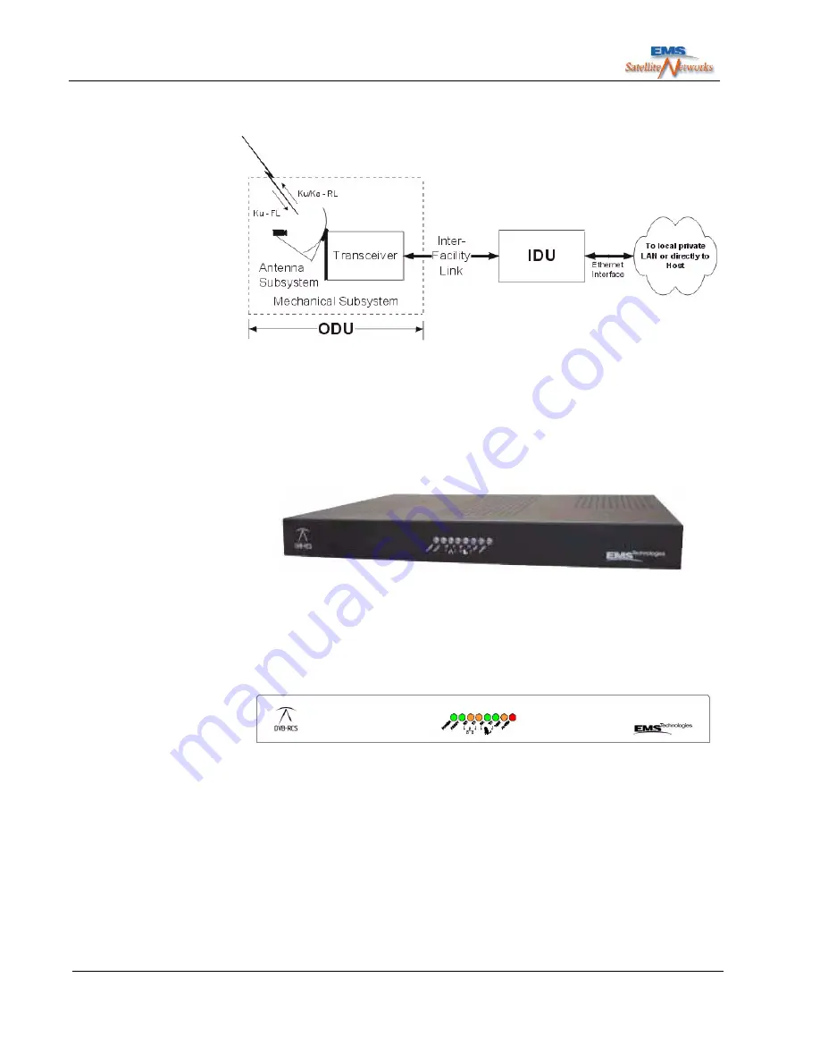
Figure 1.2 SIT Schematic Diagram
For more information about the IDU, see
section 1.4
and
Appendix E
.
1.4
IDU Overview
1.4.1 Series 2000 IDU
Figure 1.3 Series 2000 IDU
The Series 2000 IDU has a 1U rack-mount form factor. The front panel contains 8 indica-
tor LEDs. Power and cable connections are at the back of the unit.
The figure below shows a schematic diagram of the IDU front panel.
Figure 1.4 Front View - Series 2000 IDU
The front panel contains the following LEDs (from left to right).
• Power LED - Green. Indicates power on when lit.
• IDU Ready - Green. Indicates IDU is ready when lit. When flashing it indicates the
SIT is in “Hold” state.
• Ethernet Rx - Amber. Indicates that the IDU ethernet interface is receiving traffic
from host when lit.


