background image


Manual-EMT-PRO-Tonearm 

4/13 

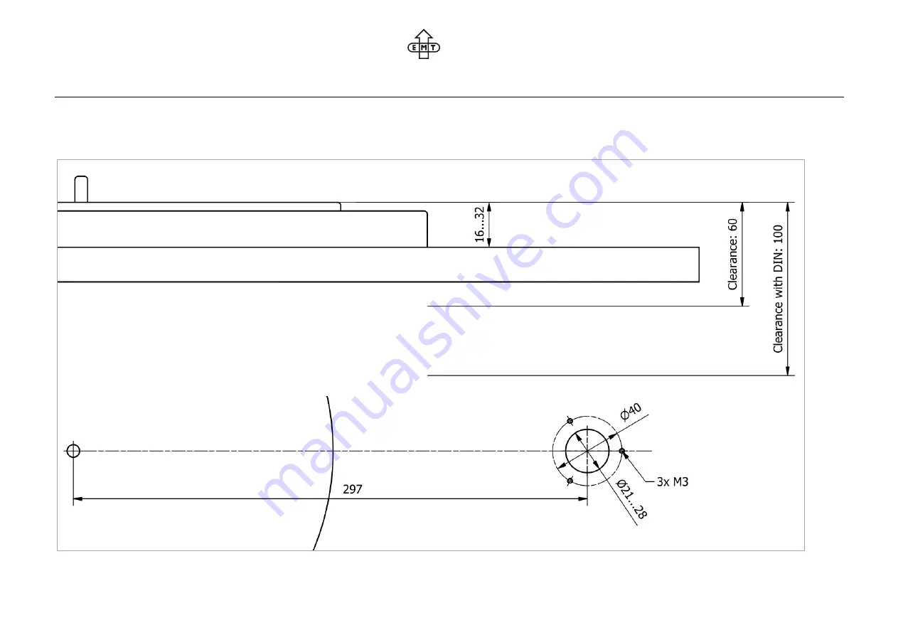
Tonearm-base EMT 912 (12-inch version) 

Prepare the tonearm-base of your turntable according to the drawing below. If anything is unclear or if you have questions, please contact your dealer. 


Summary of Contents for 909

Page 1: ...EMT 912 Professional 12 inch tonearm with quick coupling system for EMT Tondose Thank you for choosing the EMT tonearm Please take time to install and adjust your product properly remember to work carefully and to follow the instruction manual step by step You will find actual information about our products on www emt tontechnik ch ...

Page 2: ...he device to improper use or malfunction caused by neglecting the instructions elsewhere in the user manual Unauthorized disassembly or modifications whatsoever of the product will also avoid the warranty In any case of warranty claims please contact your dealer Package contents Remove the top layer of the packaging inlays The package contents 1 Tonearm 2 Counterweight 3 Base ring incl retaining s...

Page 3: ...l EMT PRO Tonearm 3 13 Tonearm base EMT 909 9 inch version Prepare the tonearm base of your turntable according to the drawing below If anything is unclear or if you have questions please contact your dealer ...

Page 4: ... EMT PRO Tonearm 4 13 Tonearm base EMT 912 12 inch version Prepare the tonearm base of your turntable according to the drawing below If anything is unclear or if you have questions please contact your dealer ...

Page 5: ...M3x6 if the threads in the turntable are shorter than 10mm 3x M3x10 if the thread in the turntable are longer than 10mm 2 Place the Base ring on the tonearm base 3 Align the Base ring in relation to the turntable chassis Refer to the orange lines in the drawing 4 Tighten the three screws to fix the Base ring 1 2 3 ...

Page 6: ...must not protrude into the hole Refer to picture 1B for correct position 2 Insert the Tonearm into the Base ring The groove in the shaft should be aligned with the retaining screw Refer to the orange markings in picture 2 3 Carefully tighten the retaining screw Make sure the bolt of the screw fits into the groove as shown in picture 3 1A 1B 2 3 ...

Page 7: ...ut Connector Option DIN As an option your tonearm is delivered with a 5 pin DIN connector If required the axial orientation of the connector can be changed according the procedure below 1 Remove the six countersunk head screws holding the DIN adapter 2 Carefully turn the DIN adapter into the required position Make sure not to pull the internal wiring 3 Insert the six countersunk head screws again ...

Page 8: ...stem of your tonearm 2 Turn the coupling ring counter clockwise to lock the cartridge Cartridge Types As a product of the EMT professional product line your tonearm is designed to be connected with professional cartridge types 1 EMT Standard this is the standard configuration of the EMT profes sional tonearm 2 INT Option this connection is Ortofon A compatible and available for the EMT professiona...

Page 9: ...ion by turning the complete lifting device 15 Tighten the slotted screw 1 gain Removing Device Remove the slotted screw 1 Remove the complete lifting device Vertical and axial position Choose the hex key wrench 1 5mm from the accessories box Release the hexagon screw 2 Move the lift cylinder in the correct vertical and axial position Carefully tighten the hexagon screw 2 again Tighten lift support...

Page 10: ... rear end of the tonearm 2 Move the counterweight horizontally for approcimate setting Turn the counterweight clockwise to increase the VTF Turn the counterweight anticlockwise to decrease the VTF Reset the scale Turn the counterweight until the tonearm is in fully balanced position Hold the main unit 3 of the counterweight in place Turn the scale 4 until the 0 Position is aligned with the marking...

Page 11: ... a record groove To compensate for tolerances of your cartridge minor deviation from the horizontal position could be required Please ask your dealer for further information 1 Use the 2mm Hex key wrench to release the retaining screw 1 for half a turn 2 Adjsut the vertical position Turn the VTA Ring 2 clockwise to increase the height Turn the VTA Ring 2 anticlockwise to decrease height 3 Tighten t...

Page 12: ...value on the dial should refer to the vertical tracking force VTF Note The skating force is not a constant value It depends on a the vertical tracking force b the stylus shape c the groove modulation A blank disk can help to set the compensation force However in certain cases the procedure may be unsuitable especially with modern stylus shape such as Super Fine Line or Multi Radius In such cases w...

Page 13: ...ngth 246 75mm 310 15mm Effective mass 10 3g 11 7g Offset angle 22 25 17 55 Overhang 16 75mm 13 15mm Outer null point 120 9mm Inner null point 66 04mm Connection Standard EMT Tondose Option INT Ortofon A compatible Output Standard wire outlet 20cm Option DIN 5 pin DIN outlet Version V1 3 Date 02 08 2022 ...

Reviews: