background image

AMETEK CTS 


BS 200N100  


Operating manual 

V 1.12 

16 / 21 


7.2. 

LV 124 Test E-10 short interruption Text case 3  

The LV124 is a cooperated standard of all German car manufacturers. The application note AN 213 describes in 
detail the tests with E-10 and E-13. The following chapter describes the test using the BS200N100 
 

EM Test proposal for Test case 3 with 0.1

Ω resistor 

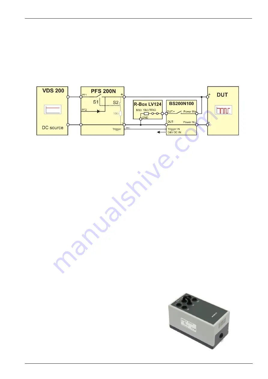
This proposal is not exact as it is in the LV 124 standard, because the 0.1Ω resistor is only during the interruption 
time in the circuit. This disadvantage allows the using of smaller dc sources. It is not necessary to drive a 
constant 110A current into the 0.1Ω resistor.  


Figure 7.4: EM Test proposal for test setup for test case 3 


Test setup and cabling 

DUT is connected wired with the PFS200 and BS200N100 as shown in figure 7.4.  

Cabling 

+ pole

 (PFS200N)  

to 

DUT +


DUT+


to 

Power IN+

 (BS200N100) 

DUT+

 (BS200N100) 

to 

Input

 (R-

Box LV124, Box set to 0.1Ω) 

GND

 (R-Box LV124)  

to 

– pole

 (PFS200)  

DUT-

 (BS200N100) 

to 

– pole

 (PFS200) 

DUT-


to 

Power IN-

 (BS200N100) 

BNC cable: PFS200 trigger to Trigger IN (BS200N100).  


Settings on BS200N100: 

Switch Mode:  NO Normally Open 
Trigger Mode:  MAN / Ext. 
Duration: 

Synchronous with trigger signal PFS200 (Power ON BS200N100 as per note below) 

Test: 

ON 

 
Power ON BS200N100: 

The BS200N100 must work synchronous with the trigger IN signal. For set the 
BS200N100 into the LV 124 mode, the user must press the 

“Manual Trigger”

 button 

during connect the power to the BS 200N100. A short LED blinking with an acoustic 
beep confirms the correct LV 124 mode. The potentiometer time setting is disabled in 
this mode. 


Function BS200N100 

The Trigger IN controls the ON / OFF position of the 
switch. The trigger signal is generated from the PFS200 
power fail generator. 


Figure 7.5: R-Box LV124 


Summary of Contents for BS 200N100

Page 1: ...y lines of a Device Under Test DUT A device under test which is considered a potential source of conducted disturbances should be tested according to ISO 7637 part 2 The BS 200N100 and BS 200N100 1 include an electronic switch for repeatable switching of inductive loads as specified in ISO 7637 2 2011 yet supporting former standard editions ISO 7637 1 1990 ISO 7637 2 1990 ISO 7637 2 2004 ISO 7637 ...

Page 2: ...manual V 1 12 2 21 AMETEK CTS GmbH Sternenhofstrasse 15 4153 Reinach BL1 Switzerland Phone 41 61 717 91 91 Fax 41 61 717 91 99 URL http www emtest com Copyright 2017 AMETEK CTS GmbH All right reserved Specifications subject to change ...

Page 3: ...t voltage 11 5 3 Switch Off fall time 11 5 4 Measuring results 12 5 4 1 Voltage drop in dependence of the test load 12 5 4 2 Measuring results with verification set up as per Standard 12 5 4 3 Verification 12 6 Maintenance 13 6 1 General 13 6 2 Calibration and Verification 13 6 2 1 Factory calibration 13 6 2 2 Guideline to determine the calibration period of EM Test instrumentation 13 6 2 3 Calibr...

Page 4: ...es by conduction and coupling Part 2 Electrical transients conduction along supply lines only several standards In accordance with ISO 7637 Part 2 LV 124 Elektrische und elektronische Komponenten in Kraftfahrzeugen bis 3 5t Allgemeine Anforderungen Prüfbedingungen und Prüfungen 1 1 Maximum applicable dc voltage supply The maximum applicable DUT dc voltage supply for the BS 200N100 is 60V DC Higher...

Page 5: ...tton the BS 200N100 switch starts to work 2 Switch Mode Setting of the switch mode NO Normally Open The switch is normally open and close at each event NC Normally Closed The switch is normally closed and opens at each event 3 LED Switch closed The LED is lighted during the switch is closed 4 Manual Trigger Select Manual trigger mode of the switch open and closing time depends the time setting OFF...

Page 6: ... external voltage probe with 400MHz bandwidth must be used 4 CRO Trigger OUT Trigger output for an oscilloscope trigger Trigger with a negative slope 15V to 0V 5 Trigger IN The Trigger IN Umax 15V has two different modes 1 External trigger input for start a single switch event using the duration setting with the potentiometer The trigger shall be a zero going signal BNC to GND 2 Direct switch cont...

Page 7: ...n or by remote trigger The electronic switch can switch currents up to 100A and is able to withstand voltages up to 1000V The electronic switch is protected against overload and can withstand short circuit conditions Specific protection requirements of the EUT must be separately assured by the user Inrush currents Inrush currents up to 500A are permitted Overvoltage The switch is protected against...

Page 8: ...n 10 ms to 500 ms continuously selectable by potentiometer 5 On Off repetition Min 1 s to 10 s continuously selectable by potentiometer 5 Operation Switch closed indicated by LED Output noise 400 mV peak typical 300 mV Trigger Manual Manual trigger of a single event Auto Automatic trigger with min 0 1 Hz to max 1 Hz repetition continuously selectable by potentiometer Extern External trigger 0V BNC...

Page 9: ...iance ErP level V Number of Outputs 1 4 2 Technical data CA BS 200N Test voltage Battery supply voltage 28Vdc max Load current 50A max Operating time 13 5V supply approx 1 hour 28 0V supply approx 10 minutes Overheat indication LED Protection Switch Off by over temperature sensor Cooling Forced air temperature controlled Impedance Load 0 6 in series with 50 H selectable with bridge R L Parallel lo...

Page 10: ...V 60V 3A 1 5A 1 25A 0 5A 90W 45W 62 5W 30W Cooling passive Max Temperature 30V continuous approx 50deg max 50V continuous approx 90deg max General data Dimensions 300 x 105 x 90mm L x W x H Weight 1 70kg 4 4 R Box LV124 Resistor box Resistance 0 1Ω 10kΩ 100kΩ Max Spannung 60V 60V 60V Load at Vmax continuous continuous Max load 5W 10 min 10W 5 min General Data Dimension 150 x 80 x 80mm L x W x H We...

Page 11: ... 5 2 Test voltage According to the standard the switch Off time should be determined under varying test voltages such as Va U1 13 5V and U2 27V Consequently constant currents of 22 5A or 45A must be considered The resulting energy consumption at the test load is DC Supply Power 0 6 13 5 V 304 W 27 0 V 1215 W 5 3 Switch Off fall time The switch Off fall time is specified as follows 90 to 10 ISO 763...

Page 12: ...rve illustrated have been recorded with a serial model Reference values measured with BS 200N100 Input Voltage 13 5 V Output Voltage 13 30 V Upeak 1030 V tf 90 10 327 4 ns Figure 5 3 Pulse parameter 5 4 3 Verification Verification as per ISO 7637 2 Ed3 2011 03 is defined at 13 5V only Verification must be performed with calibration load CABS 0 6 in series with 50 H Rshunt not used Verification wit...

Page 13: ...refore the customer needs to specify the calibration interval for his test equipment In reply to all these questions we like to approach this issue as follows EM TEST make use of a solid state semiconductor switch technique to generate high voltage transients A precious advantage of this technique is the absolute lack of periodical maintenance effort In consequence thereof a useful calibration per...

Page 14: ...low impulses in the ms range is before the electrical switch see figure 7 1 For fast impulses in s and ns range the switch is on the DUT side figure 7 2 During the examination only one switch may be operated For the emission measurement ISO 7637 2 2011 defines the test setup below EM Test propose the test setup illustrated in figure 7 1 7 2 and 7 3 Figure 7 1 Setup for pulses in the ms range Figur...

Page 15: ...high amplitudes arise with fast pulses which can be limited by the protection device of the electrical switch Therefore the standard recommends to use the original switch how it is used in the vehicle as switching device for pulses in s ns range If such a device is not available an automotive relay with the following characteristics shall be used contact rating I 30 A continuous resistive load hig...

Page 16: ...nd BS200N100 as shown in figure 7 4 Cabling pole PFS200N to DUT DUT to Power IN BS200N100 DUT BS200N100 to Input R Box LV124 Box set to 0 1Ω GND R Box LV124 to pole PFS200 DUT BS200N100 to pole PFS200 DUT to Power IN BS200N100 BNC cable PFS200 trigger to Trigger IN BS200N100 Settings on BS200N100 Switch Mode NO Normally Open Trigger Mode MAN Ext Duration Synchronous with trigger signal PFS200 Powe...

Page 17: ... 1 BS 200N100 Mains adapter 24V dc Plug Type CH AUS EURO UK USA Figure 8 2 Supply adapter 4 connection clamps for assembling 2 connection bridge 6mm BS200N100 to AN 200N100 with junction 4mm to a load resistor Rs Figure 8 3 connectors Identical accessory parts are delivered only once if several devices are ordered The delivered packing list is in each case valid for the delivery ...

Page 18: ...rtificial Network LISN Impedance As per ISO 7637 2 ISO 11452 2 CISPR16 1 2 CISPR 25 Impedance 5 H 50 Current 100A continuous Figure 8 6 AN 200N100 Shunt resistor Rs Shuntresistor for simulate the resistance of other vehicle devices which are connected in parallel to the DUT The standard ISO 7637 2 defines the shuntresistor Rs RS Box 10Ω 20Ω 40Ω 120Ω max 60V 30V Figure 8 7 RS Box R Box LV124 Resist...

Page 19: ...ed EN 61010 1 2011 Safety requirements for electrical equipment for measurement control and laboratory use EMC Directive 2014 30 EU Standard s to which conformity is declared EN 61326 1 2013 Electrical equipment for measurement control and laboratory use Class A EN 61000 3 2 2014 Limits for harmonic current emissions EN 61000 3 3 2013 Limitation of voltage changes voltage fluctuations and flicker ...

Page 20: ...AMETEK CTS BS 200N100 Operating manual V 1 12 20 21 9 2 BS 200N100 Overview Figure 9 1 Overview BS 200N100 ...

Page 21: ...AMETEK CTS BS 200N100 Operating manual V 1 12 21 21 9 3 CA BS Overview Fig 9 2 Overview CA BS ...

Reviews: