


EMTRON EIC USER MANUAL
WWW.EMTRON.WORLD
© EMTRON AUSTRALIA PTY LTD APRIL 2018
11
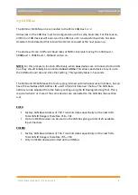
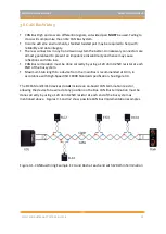
3.6 Noise Immunity
To minimise signal contamination and maximise noise immunity, the wire pairs shown in
Table 3.2 must be twisted. It is recommended to twist the wire pairs at a minimum one twist
per 40mm of cable. This is very important and should always be implemented.
Pair 1
Pair 2
CAN High
<-------> CAN Low
Table 3.3. CAN Hi and Lo wire pairing for twisting
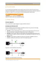
3.7 Sensor Wiring
5V Sensor Supply Pin
This is a 250mA 5V output designed to supply automotive sensors.
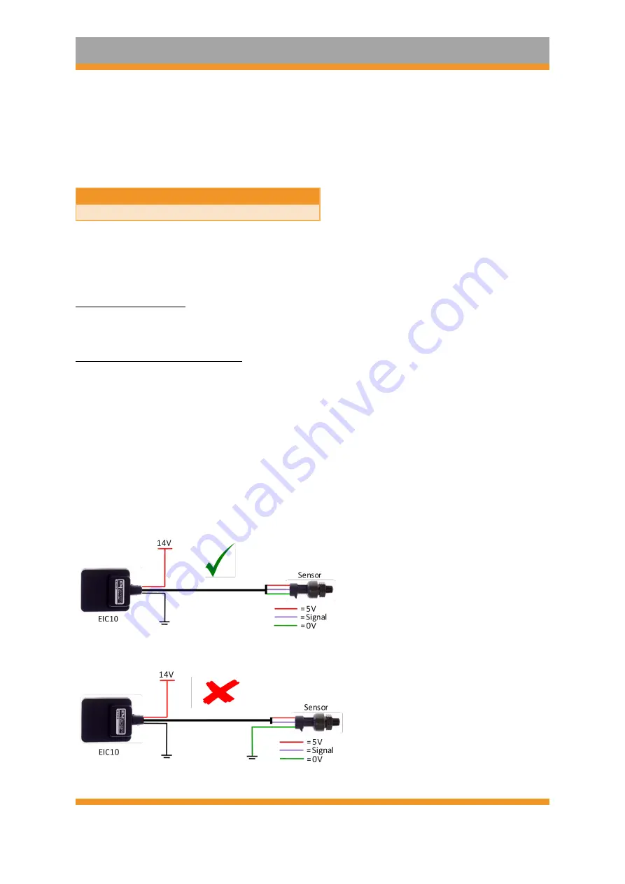
Analog Sensor 0V Reference Pin
This pin should be connected directly to the 0V (Ground) pin on any low current analog
sensor, for example Pressure or Temperature.
•
DO NOT
connect the EIC 0V Reference pin directly to the Engine Block or ECU Ground.
This is a dedicated and specialised 0V/ground output for analog sensors.
•
DO NOT
connect a sensor 0V/ground pin directly to the Engine Block or Device Ground.
Instead this pin should be directly connected to the dedicated EIC 0V Reference pin. See
Figure 3.1/3.2.
•
DO NOT
connect frequency based sensor grounds to the EIC 0V Reference pin; for
example, an Ethanol content sensor. Use the main device ground.
Figure 3.1. Correct MAP Sensor 0V Wiring
Figure 3.2. Incorrect MAP Sensor 0V Wiring


