EMTRON EIC USER MANUAL
WWW.EMTRON.WORLD
© EMTRON AUSTRALIA PTY LTD APRIL 2018
17
4.21 EIC Multiple Device Detection
The following example uses the EIC10. Connect to the ECU using Emtune. Open the ECU
Runtime menu (F3) and select the Communications Tab. Within this tab will be a list of
Emtron CAN devices that the ECU has detected. It will list:
1.
CAN Device Model
2.
Device Serial Number
3.
Device Firmware Version
4.
Device Hardware Version
5.
CAN Base Address
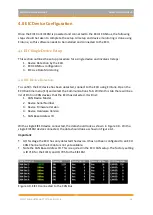
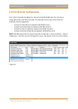
With 2x EIC10 devices connected to the CAN bus, the CAN Summary List should look similar
to that shown in Figure 4.6. In this example the following devices have been detected:
▪
Device 1 - SN 1230
▪
Device 2 - SN 1225
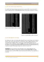
Figure 4.6
Example showing two EIC10 devices detected by the ECU
Note:
ALL devices have the same Base Address of ID 718, which is the factory setting for a
single device. To avoid Bus conflicts, the factory base address needs to be changed when
multiple devices are used, to ensure each device has its own unique ID. When re-
programming the Base Address for each device the IDs MUST be:
1)
Sequential in order.
2)
Have a gap of 4 numbers between each EIC10 device.
(Doesn’t apply to EIC16M as only one device permitted on the Bus)
The Base Address ID can be any number but Emtron recommends the following:
•
EIC10 Device 1: ID Base Address 718. (CAN ID Range 718-721)
•
EIC10 Device 2: ID Base Address 722. (CAN ID Range 722-725)
The following Base Address is recommended for the EIC16M devices:
•
EIC16M Device 1: ID Base Address 705 (CAN ID Range 705-710)

