EMTRON EIC USER MANUAL
WWW.EMTRON.WORLD
© EMTRON AUSTRALIA PTY LTD APRIL 2018
8
3.3 CAN Bus
The EIC10 or EIC16M can be connected to the ECUs CAN Bus 1 or 2.
All devices on the CAN Bus must be configured to use the same baud rate. For this reason,
all Emtron CAN devices will Auto-scan the CAN bus until a successful baud rate has been
detected. Once detected this rate will be stored and used at the next power up.
The device will scan 3 different Baud rates at 500ms intervals moving from 1Mbaud ->
500kBaud -> 250k Baud -> 1Mbaud and so on.
NOTE:
For this process to function effectively, when
new
devices are introduced to the CAN
bus, they should initially be connected
one at a time.
This allows each device to sync up to
the CAN Bus baud rate and store that setting. This typically takes 3-5 seconds.
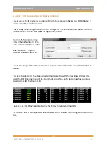
The EIC10 and EIC16M leave the factory programmed with individual serial numbers, but all
have the same Base CAN Address ID used to transmit data over the Bus. The CAN Base
address can be adjusted from the factory setting using the ID Reprogramming Tool. This is
required when 2 or more of the same devices are connected to the CAN Bus (See section
4.2)
EIC10
.
▪
Factory CAN Base Address of 718. Transmits data sequentially on the next 3 IDs.
Total CAN ID Range is therefore 718
–
721.
▪
Up to 2x EIC10 devices can be used on the CAN Bus giving a total of 20 available
Input Channels.
EIC16M
.
▪
Factory CAN Base Address of 705. Transmits data sequentially on the next 5 IDs.
Total CAN ID Range is therefore 705
–
710.
▪
Only 1 EIC16M device permitted on the CAN Bus.

