EMTRON ELC USER MANUAL
WWW.EMTRON.WORLD
© EMTRON AUSTRALIA PTY LTD MARCH 2018
21
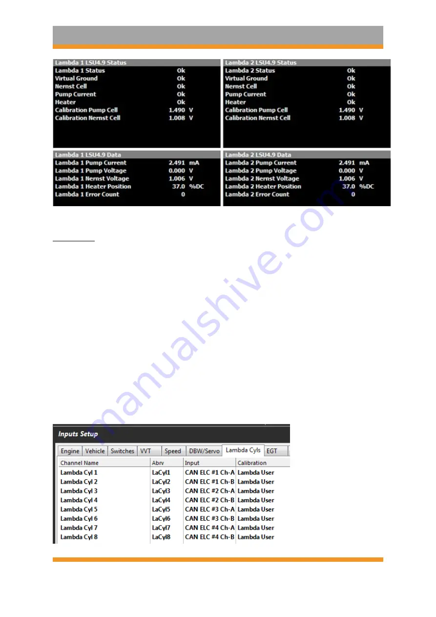
Figure 8.1
Options B:
Use the Lambda Cylinder Input Channels. This setup is normally done when
multiple ELC devices are used to measure the lambda on individual cylinders. Figure 8.2
shows four ELC devices configured, measuring the individual Lambda on an 8-cylinder
engine. Example setup:
▪
To configure the ELC Device 1:
o
Channel A to Cylinder 1; set the Channel Input Source for Lambda Cyl 1 to
CAN
ELC #1 Ch-A
o
Channel B to Cylinder 2; set the Channel Input Source for Lambda Cyl 2 to
CAN
ELC #1 Ch-B
▪
To configure the ELC Device 2:
o
Channel A to Cylinder 3; set the Channel Input Source for Lambda Cyl 3 to
CAN
ELC #2 Ch-A
o
Channel B to Cylinder 4; set the Channel Input Source for Lambda Cyl 4 to
CAN
ELC #2 Ch-B
… etc for ELC Device 3 and 4
Figure 8.2. Multiple ELC devices channel assignments


