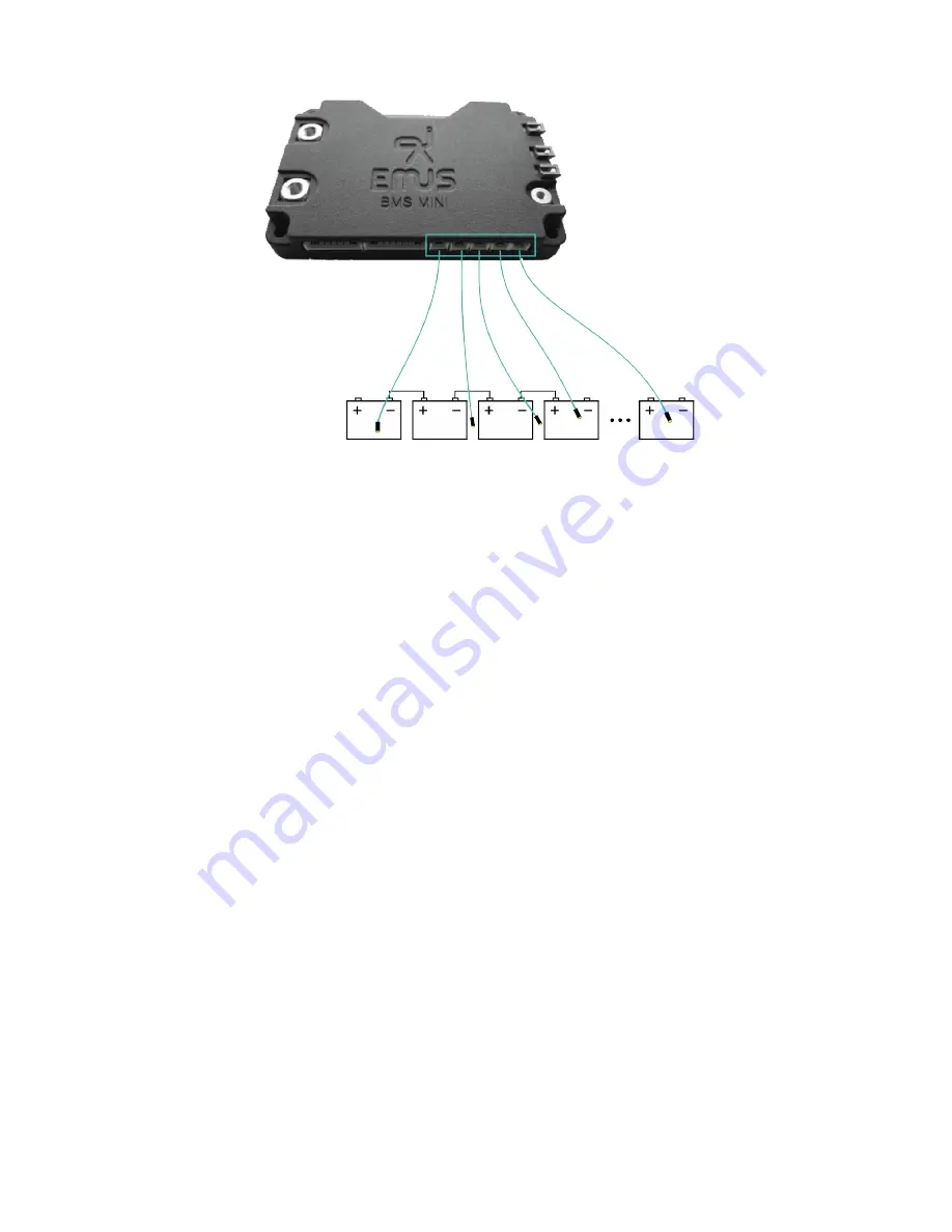
Figure 2.5: External Temperature Sensor installation diagram
2.3
Charger installation
Charging process control is one of the most important tasks that a battery management system
must perform to ensure safe lithium battery operation, therefore it is very important to correctly
select and connect a charging device in order allow EMUS BMS mini to control it. The selection
of a particular charging device should be done considering various aspects of the application, yet its
output parameters are the most important from the battery management system’s point of view. The
maximum charger’s output voltage should be slightly higher than the cell charge voltage specified
in the cell specification sheet multiplied by the number of cells connected in series. The maximum
charger’s output current should not exceed the maximum charging current specified in the same
specification sheet. Correct connection of different charging devices types supported EMUS BMS
mini is described in the following chapters.
2.3.1
Non-CAN based charger
Non-CAN charger can be integrated with EMUS BMS mini in 2 different scenarios: using additional
components to control the charger or without control. Main differences of these two scenarios are
described below:
1. When using Non-CAN charger without control BMS cannot perform charger switching, also
battery pack does not reach full potential of balanced cells.
2. When using Non-CAN charger with additional components for control, BMS can perform
charger switching, and total battery cell balance is reached, but with relatively slower balancing
process.
Scenario 1 (uncontrolled Non-CAN charger)
In the following figure
2.6
a system using uncontrolled Non-CAN charger is presented. In this
scenario Non-CAN charger is directly connected to the battery pack. BMS has no control over
charger’s output voltage or current. Therefore, when the battery pack is nearly fully charged these
events will happen: because this type of charging is uncontrolled, balancing is not efficient and
9


