4
Data interfaces
BMS mini uses CANopen protocol for communications through listed interfaces (except LIN). Device
has it’s object dictionary supporting various parameters viewing and configuring. Each interface
caries CANopen packets and has access to all available device features. All interfaces can be
accessed asynchronously and independently to each other.
4.1
Wireless smartphone connectivity
2.4 GHz integrated wireless interface is designed to connect with smart-phones and PCs supporting
the same wireless technology. "EMUS BMS mini" application has to be installed in order to connect
BMS mini device used for information display and configuration. Smartphone acts as a CANopen
client and communicates through EMUS BMS mini object dictionary. Interface works as serial
transmission channel and transfers standard CANopen packets back and forth. Wireless interface
also enables features like discovering currently enabled BMS mini devices in range and displays their
customizable names and serial number for easier identification. It’s worth notice that only one
wireless client (e.g., smart-phone) can be connected at the time. BMS mini will not be discoverable
until primary device disconnects. However, other interfaces will still be available.
4.2
CAN
The CAN bus has be widely adopted in industrial, automotive, and instrumentation applications
due to the inherent strengths of its communication mechanisms, however its reliability will be com-
promised if it is not set up correctly. CAN-equipped Emus BMS components are designed to be
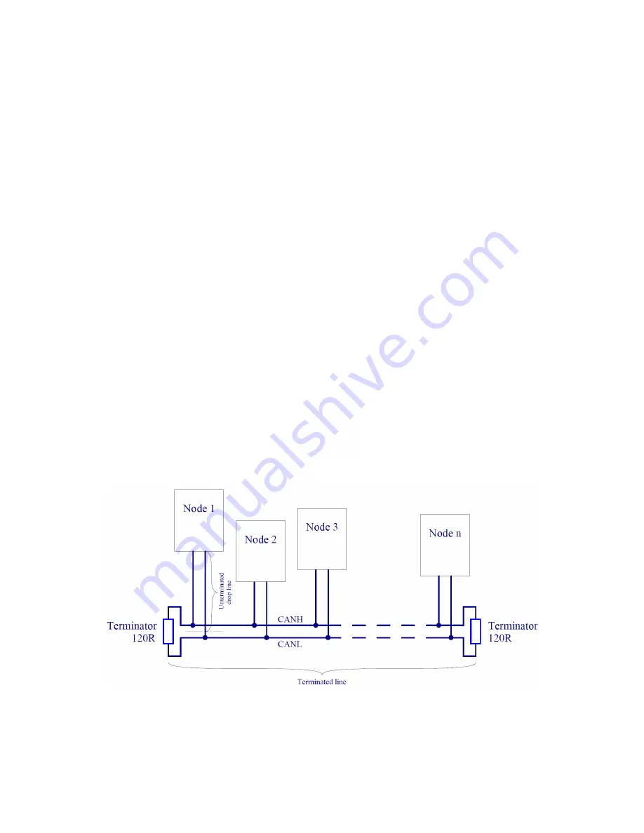
used in high-speed CAN networks, such as the one specified by the ISO 11898-2 standard. This
standard defines a single line structure network topology in which the bus lines are terminated at
their furthest ends by a single termination resistor, as shown in figure
4.1
.
Figure 4.1: High-speed CAN network specified in ISO-11898-2 standard
The maximum total bus length and maximum lengths of a single unterminated drop line and all
unterminated drop lines together of a CAN network to which Emus BMS components are connected
are presented in the Table
4.1
. Maximum total bus length is essentially limited by propagation
20


