background image

EMX Industries, Inc. 

Tech support: 216-834-0761 

1/8


IRB-RET_Rev2.0_080619                                      technical@emxinc.com


IRB-RET  

   Universal Retroreflective Photoeye 


Instruction Manual 

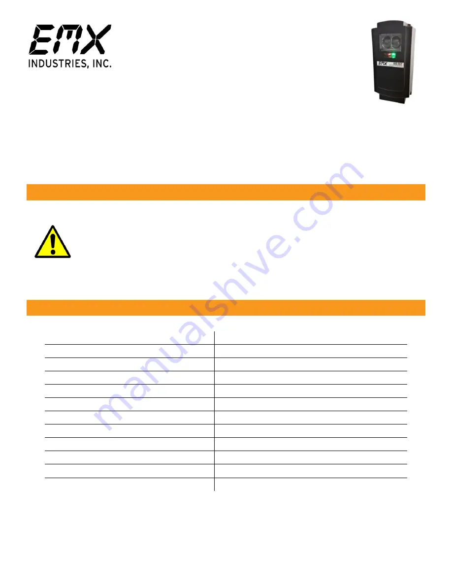
The  IRB-RET  retroreflective  infrared  photoeye  is  an  external  entrapment  protection  device  type  B1,  
non-contact sensor for use with automatic gates and doors. Since the reflector directs the beam back to 
the photoeye, wiring to the other side of the roadway is not needed. The IRB-RET operates up to 60 feet 
over  a  wide  range  of  voltages  (6-40  VDC  and  12-24  VAC).  A  red  alignment  indicator  on  the  receiver 
provides  status  information  at  a  glance,  making  set-up  and  alignment  easy.  The  IRB-RET  provides 
compatibility with most operators that accommodate monitored external entrapment devices per UL325. 

Cautions and Warnings 


This product is an accessory or part of a system.  Install the IRB-RET according to instructions 
from the gate or door operator manufacturer. Comply with all applicable codes and safety 
regulations.  


Retroreflective  photoeyes  rely  on  a  reflective  surface  (a  reflector)  for  proper  operation.  
In some cases, a vehicle with a reflective surface at a given distance can act as a reflector 
and allow the gate to close on a vehicle. 
 

Specifications 


Operating Range 

5 ft (1.5 m) to 60 ft (18.3 m) 

Power  

6-40 VDC, 12-24 VAC  

 ononly) 

Current (NC and 10K Monitoring Methods)  60 mA (relay activated) 
Current (Pulse Monitoring Methods) 

15 mA  

Resistive Termination  

10K ohm across NO contact (jumper selectable) 

Surge Protection 

Thermal fuse  

Relay Output Operation 

Light ON/Dark ON 

Relay Output Configuration 

Form C contacts (NO, COM, NC) 

Transmitter Power Cycle 

<300 mS (for use in NC and 10K monitoring) 

Methods) 


Operating Temperature 

-40° to 140°F (-40° to 60°C) 

Dimensions (L x W x H) 

3.1” (79


mm) x 2.7” (69


mm) x 6.6” (168

 mm) 


Environmental Rating 

NEMA 4X 

Summary of Contents for IRB-RET

Page 1: ...s an accessory or part of a system Install the IRB RET according to instructions from the gate or door operator manufacturer Comply with all applicable codes and safety regulations Retroreflective photoeyes rely on a reflective surface a reflector for proper operation In some cases a vehicle with a reflective surface at a given distance can act as a reflector and allow the gate to close on a vehic...

Page 2: ...facturer s instruction manual for necessary monitoring method Normally Closed Cycles power to the transmitter while monitoring the receiver contacts for proper operation 10K Resistive Termination Provides a measurable 10K ohm resistance across the normally open NO when unobstructed Two wire Pulse 2 Frequency Provides 300Hz heartbeat unobstructed 0Hz obstructed over power supply lines Two wire Puls...

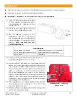
Page 3: ... obstruction Green LED Flashing Red LED Off Beam obstructed or not aligned Green LED Off No power 4 Set the sensitivity adjustment to 1 3 of the maximum by adjusting the potentiometer as shown Potentiometer Sensitivity Adjustment 5 Hold the reflector and stand 4 to 6 feet away from the IRB RET Align the reflector with the photoeye and slowly back up to the opposite end of the detection zone where ...

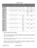
Page 4: ... will turn on 12 Check the operator control board and verify that the safety input is recognized by the operator Test the beam with an obstruction between transmitter and reflector at multiple distances to confirm proper operation 13 Follow the gate or door operator manufacturer s installation instructions and safety checks to verify that the photoeye is operating properly Configuration Settings a...

Page 5: ...using a pull up resistor to low voltage DC power Monitoring Method Wiring Diagram DIP Switch Settings Output Connections Power Connection Jumpers Installed SW1 SW2 SW3 SW4 VRX VTX JP2 JP4 JP5 JP6 Normally Closed A OFF OFF OFF ON NC COM VRX Factory Set 10K disabled 4W 10K Resistive Termination B OFF OFF OFF ON NO COM VRX Factory Set 10K enabled 4W Normally Closed Power Cycle Transmitter Only C OFF ...

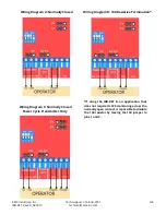
Page 6: ...rmally Closed Wiring Diagram B 10K Resistive Termination If using the IRB RET in an application that does not require UL325 monitoring across the normally open contact it is possible to disable the 10K resistor by moving the 10K jumper to pins 1 and 2 Wiring Diagram C Normally Closed Power Cycle Transmitter Only ...

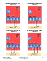
Page 7: ...6 834 0761 7 8 IRB RET_Rev2 0_080619 technical emxinc com Wiring Diagram D Two Wire Pulse 2 Frequency Wiring Diagram D Two Wire Pulse 3 Frequency Wiring Diagram E Four Wire Pulse 2 Frequency Wiring Diagram E Four Wire Pulse 3 Frequency ...

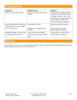
Page 8: ...wise Green LED flashes continuously indicating an obstruction when one is not present Sensitivity is too low Photoeye is not aligned with reflector Adjust sensitivity clockwise Check alignment verify operation with reflector Photoeye activates but does not transmit signal to operator Faulty connection between photoeye and operator control input Verify all wires and terminal connections to operator...

Reviews: