EMX Industries, Inc.
Tech support: 216-834-0761
3/8
IRB-RET_Rev2.0_080619 technical@emxinc.com
Installation
•
Determine the mounting location of the IRB-RET photoeye according to UL325 guidelines.
•
Deactivate the gate or door during photoeye installation.
•
The IRB-RET cannot be used for a detection range of less than 5 feet.
1.
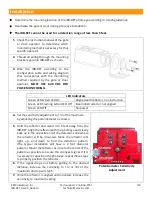
Check the instruction manual of the gate
or door operator to determine which
monitoring method is necessary for that
specific operator.
2.
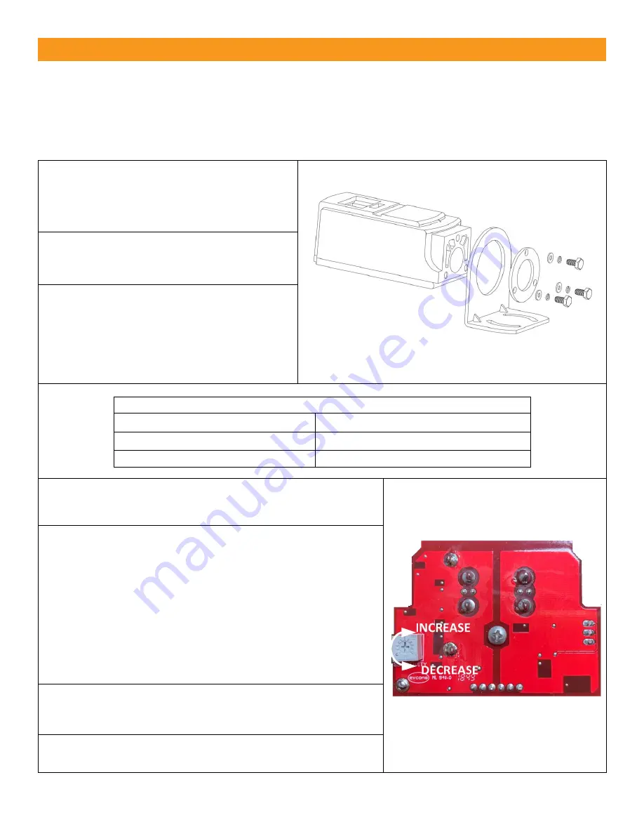
Thread all wiring through the mounting
brackets and into IRB-RET as shown.
3.
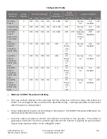
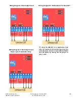
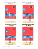
Wire the IRB-RET according to the
configuration table and wiring diagram
that corresponds with the monitoring
method required by the gate or door
operator.
MUST USE 6-40 VDC FOR
PULSE MONITORING.
LED Indicators
Green LED & Red LED On
Aligned with reflector, no obstruction
Green LED Flashing & Red LED Off Beam obstructed or not aligned
Green LED Off
No power
4.
Set the sensitivity adjustment to 1/3 of the maximum
by adjusting the potentiometer as shown.
Potentiometer Sensitivity
Adjustment
5.
Hold the reflector and stand 4 to 6 feet away from the
IRB-RET. Align the reflector with the photoeye and slowly
back up to the opposite end of the detection zone where
the reflector will be mounted. Move the reflector left,
right, up, and down to find the detection pattern.
(The typical installation will have a 2 foot diameter
pattern.) Mount the reflector as close to the center of the
pattern as possible to assure the strongest signal. If it is
necessary to reposition the photoeye, repeat these steps
to properly position the reflector.
6.
If the signal drops out before getting to the desired
distance, increase the sensitivity to 1/2 or 3/4 of the
maximum and repeat step 5.
7.
Once the reflector is aligned and mounted, increase the
sensitivity to maximum setting.


