INSTALLATION AND CONNECTION
smart Econ - emz-HCW - 180116
53
Connection CAN-Bus
All devices must be connected in the following sequence.No branches are allowed.
4-pole STP or FTP cable, e.g. J-Y(ST)Y 2 x 2 x 0.6 mm², is recommended as bus cable.
With cables of a correspondingly high quality, the total length of the bus cable can even be several
hundred meters, whereby approx. 20-25 m must be subtracted for each terminal point.
For short distances and sufficient distance (min. 30 cm) to lines carrying mains voltage, unshielded
UTP cable (unshielded twisted pair) can also be used.
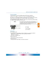
(1) + = Vss
(2) - = GND
(3) H = CAN High
(4) L = CAN Low
Cable routing
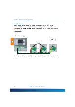
Lay the following cables:
• 4-pole CAN bus line: serial between smart Econ HCW and room controller with HCW 810,
between base unit - Expansion module - Room controller for HCW 1620
“CAN bus line” on page 15
• Power cable to smart Econ HCW
Optional for networking:
• Ethernet cable to smart Econ Userinterface
Optional configuration:
• USB cable (USB-A / Micro-USB-B) to smart Econ Userinterface
NOTE
It is important to ensure good grounding of the shielding, as
otherwise the shield can act as an antenna and even amplify
interference on the bus in case of faulty installation, e.g. by
cutting off the shielding foil or the mains.
1 2
4
3
+ -
L
H
4-pole bus line
CAN bus terminals

