background image

EN-KO Electronic Control Systems                                                                                                      

AMF 4.0/ENG/K.K./02


20

Enter  model  number  to  load  parameter  table  of  selected 
genset model. 

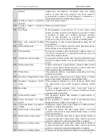
P70  Periodic service time 

This  parameters  selects  After  how  many  running  hour 
periodic service alarm will be given 

P71  Engine hour adjustment 

Engine hour is adjusted by this parameter. 

P72  Clear last ten alarm 

When you select “YES” and press menu key last ten failure 
is cleared. 

P73  Clear periodic service alarm 

When  you  select  “YES”  and  press  menu  key,  periodic 
service alarm is cleared and service time is reset 

P74  Return  to  technician  factory 

defaults 

When you select “YES” and press menu key technician 
parameters is returned to factory defaults 


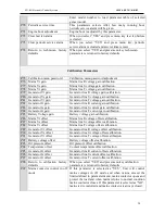
Calibration Parameters 


P75  Calibration menu password 

Calibration menu password adjustment 

P76  Mains Vr gain  

Mains line R voltage gain calibration. 

P77  Mains Vs gain 

Mains line S voltage gain calibration. 

P78  Mains Vt gain 

Mains line T voltage gain calibration. 

P79  Generator Vr gain 

Generator line R voltage gain calibration. 

P80  Generator Vs gain 

Generator line S voltage gain calibration. 

P81  Generator Vt gain 

Generator line T voltage gain calibration. 

P82  Generator Ir gain 

Generator line R current gain calibration. 

P83  Generator Is gain 

Generator line S current gain calibration. 

P84  Generator It gain 

Generator line T current gain calibration. 

P85  Battery Voltage gain 

Battery voltage gain calibration. 

P86  Mains Vr offset 

Mains line R voltage offset calibration. 

P87  Mains Vs offset 

Mains line S voltage offset calibration. 

P88  Mains Vt offset 

Mains line T voltage offset calibration. 

P89  Generator Vr offset 

Generator line R voltage offset calibration. 

P90  Generator Vs offset 

Generator line S voltage offset calibration. 

P91  Generator Vt offset 

Generator line T voltage offset calibration. 

P92  Battery voltage offset 

Battery voltage offset calibration. 

P93  Oil pressure offset 

Oil pressure offset calibration. 

P94  Temperature offset 

Coolant temperature offset calibration. 

P95  Generator Ir offset 

Generator line R current offset calibration. 

P96  Generator Is offset 

Generator line S current offset calibration. 

P97  Generator It offset 

Generator line T current offset calibration. 

P98  Return  to  calibration  factory 

defaults 

When you select “YES” and press menu key calibration 
parameters is returned to factory defaults 

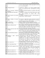
P99  Mains  contactor  control  in  off 

mode 

If  this  parameter  is  selected  as  “YES”,  Unit  will  control 
mains  voltages  in  off  mode  and  when  mains  exceed  the 
limits defined in parameter menu, mains contactor opens and 
protect the load and when mains returns to normal condition 
mains contactor closes. If this parameter is selected as “NO”, 
mains isn’t controlled and mains contactor is always closed. 


Summary of Contents for AMF 4.0

Page 1: ...ature and engine hour Generator is monitored constantly and when generator or mains values exceed the limits adjusted in the parameter menu necessary actions are taken and alarm is activated Last ten alarms are recorded in the device memory All operating modes and timings can be adjusted in the parameter menu This flexibility is provided for different kinds of generator applications FUNCTIONS Manu...

Page 2: ...h temperature failure Charge fail warning Low oil pressure failure Periodic service time warning Auxiliary failure AMF 4 0 CONNECTION DIAGRAM AMF 4 0 Generator Contactor Relay Mains Contactor Relay G R S T N U V W N LOAD R S T N GENERATOR MAINS 12 23 19 18 17 22 11 14 35 34 33 32 31 30 29 28 27 26 25 24 Configurable Input 1 Default Oil Pressure Switch Configurable Input 3 Battery 1 2 Oil Pressure ...

Page 3: ...crank or preset cranking time when you press button Start button can be used in manual mode and when engine is not running Panel will display Str message during cranking Stop Button This button is used to stop the genset When you pressed this button first time panel switched to manual mode and if generator contactor is used before genset is switched to cooling mode If you pressed second time gense...

Page 4: ...ilure level to maximum oil press sender level Display Leds These leds are in the right side of numerical displays Leds indicates meaning of the value in the displays Values in the displays can be changed by up down and menu buttons Measuring Mode Button 8 The button selects the displayed values at lower 2 numerical display These displays can show generator voltage and frequency or mains voltage an...

Page 5: ...ons 9 These are manual hand mark automatic A letter and test buttons These buttons set running mode of genset There is mode indication leds near each of these buttons When panel is in off mode you can press these buttons to wake up panel and genset will run in selected mode REAR CONNECTIONS I T I S I R I R I T I S 30 31 32 33 34 35 22 23 24 25 26 27 28 29 G 11 12 13 14 15 16 17 18 19 20 21 CRANKIN...

Page 6: ... Cont NO Output terminal of generator contactor relay This output is connected to generator contactor 15 Charge Fail Excit Warning lamp output of charge alternator must be connected here In the cranking excitation current is supplied to charge alternator over 150 ohm resistor 16 Aux Input 1 Multiple function auxiliary input These inputs are activated if it is connected to battery negative If oil s...

Page 7: ...ator line and neutral are connected to these terminals 30 31 32 33 34 35 Current Transformer Inputs Secondary side of current transformer must be connected here Each transformer must be connected separately Note Battery negative must be connected to earth RUNNING MODES Automatic Mode If you press automatic button marked A genset will switch to automatic mode In this mode panel controls mains volta...

Page 8: ...gnals is detected Panel detects engine is running crank disconnects and switch to engine stabilization time Generator status led starts to blink During cranking Str message is shown in the display Oil pressure can rise before engine running so when oil pressure is detected crank disconnected after crank disconnect oil pressure delay 4 Stabilization After generator running signals detected panel wa...

Page 9: ...his alarm occurs that means panel couldn t start or stop engine All engine signals must be absent and engine must be still before cranking If one of the engine signals is detected before cranking panel switch to start and stop alarm Panel will show which signal is detected with engine start stop alarm If oil pressure signal is detected before cranking panel will wait for it to decrease to zero If ...

Page 10: ...ssword to these sections and enter to these sections by its passwords In parameter section leftmost digit starts to blink If you press up and down buttons you can increase and decrease the value shown in the blinking digit If you want to proceed to digit at one step right menu button must be pressed You can adjust this digit up and down buttons and then you press menu button again If you are in th...

Page 11: ... 9 Mains available 10 Emergency stop 11 Cabinet thermostat alarm 6 P8 Auxiliary input 2 function Same as auxiliary input 1 0 P9 Auxiliary input 3 function Same as auxiliary input 1 10 P10 Auxiliary input 4 function Same as auxiliary input 1 4 P11 Auxiliary input 1 activation method 0 Close to activate 1 Open to activate 0 P12 Auxiliary input 2 activation method Same as auxiliary input 1 0 P13 Auxi...

Page 12: ...password 0 999 060 P45 Analog Oil sender type 0 Analog oil sender disabled 1 Analog Endiksan type 2 Analog Olcusan VDO 7 Bar type 3 Analog Olcusan VDO 10 Bar type 4 Analog Olcusan VDO 80 PSI type 5 Analog VDO 5 Bar 6 Analog AKSA type 6 P46 Oil switch type 0 Oil switch disabled 1 Normally closed for low pressure 2 Normally open for low pressure 0 P47 Low oil pressure level 0 1 9 5 bar 1 2 bar P48 A...

Page 13: ... 9 99 0 87 P80 Generator Vs gain 0 01 9 99 0 87 P81 Generator Vt gain 0 01 9 99 0 87 P82 Generator Ir gain 0 01 9 99 3 53 P83 Generator Is gain 0 01 9 99 3 53 P84 Generator It gain 0 01 9 99 3 53 P85 Battery Voltage gain 0 01 9 99 0 54 P86 Mains Vr offset 29 29 V 0 P87 Mains Vs offset 29 29 V 0 P88 Mains Vt offset 29 29 V 0 P89 Generator Vr offset 29 29 V 0 P90 Generator Vs offset 29 29 V 0 P91 Ge...

Page 14: ...8 2 P62 100 P63 1 P64 98 25 P48 2 P62 100 P63 1 P64 99 26 P48 2 P62 125 P63 1 P64 103 27 P48 2 P62 150 P63 1 P64 144 28 P15 1 P62 100 P53 0 P45 3 P64 17 P48 2 P67 9 P52 1 P68 15 29 P15 1 P62 100 P53 0 P45 3 P64 23 P48 2 P67 9 P52 1 P68 15 30 P15 1 P62 100 P53 0 P45 3 P64 48 P9 10 P48 2 P67 9 P52 1 P68 15 31 P15 1 P62 100 P45 6 P64 51 P48 2 P68 15 P52 1 P67 9 32 P15 1 P62 100 P45 6 P64 65 P48 2 P68...

Page 15: ...ameter selected 1 panel will perform preheating for Preheat time P7 Auxiliary input 1 function It selects function of auxiliary input Auxiliary input can be adjusted as red or yellow alarm Activation time can be always active active from engine starting or active from engine stabilization time When input activates auxiliary input led lit and A1 A2 A3 or A4 message is shown according to activated a...

Page 16: ...Same as auxiliary input 1 P14 Auxiliary input 4 activation method Same as auxiliary input 1 P15 Auxiliary output 1 function This parameter select the functions of auxiliary output 1 Engine running If engine running signal generator voltage frequency or charge alternator warning lamb voltage is detected this output will be activated Panel is in auto or test mode If panel is in automatic or test mod...

Page 17: ...oad transferred to mains P27 Preheat time This parameter defines in automatic preheating how long preheating continues P28 Generator voltage failure delay When generator voltages are out of voltage limits a voltage alarm is given after generator voltage failure delay P29 Generator frequency failure delay When generator frequency is out of frequency limits high low speed alarm is given after genera...

Page 18: ...h input is transferred to analog oil pressure sender input P46 Oil switch type Oil pressure switch type can be selected from this parameter P47 Low oil pressure failure If oil pressure fall below this limit Oil pressure failure alarm is activated P48 Analog temperature sender type Analog coolant temperature sender can be selected from this parameter If genset has only digital coolant temperature s...

Page 19: ...ed all engine running signals absent panel will wait an additional protection delay This is necessary for engine to stop completely before next engine start Do not decrease this value if not necessary P62 Current transformer primary This parameter contains current transformer primary value If Current transformer primary is more than 999 you must change parameter menu current multiplier to x10 mode...

Page 20: ...gain calibration P84 Generator It gain Generator line T current gain calibration P85 Battery Voltage gain Battery voltage gain calibration P86 Mains Vr offset Mains line R voltage offset calibration P87 Mains Vs offset Mains line S voltage offset calibration P88 Mains Vt offset Mains line T voltage offset calibration P89 Generator Vr offset Generator line R voltage offset calibration P90 Generator...

Page 21: ...50VAC 10 A Voltage measurement 20 300VAC Frequency measurement 1 99 Hz Current measurements 5 A current inputs current transformer should be used Connection Screw socket Measurement Accuracy Phase voltages 2 Frequency 0 1Hz Phase currents 2 Charge Excitation Current 80mA 12VDC 160mA 24VDC Housing PPO Polyphenylene oxide 30 Glass Fiber Protection Class IP 52 Front side Weight 600 gr aprox Dimension...

Page 22: ...EN KO Electronic Control Systems AMF 4 0 ENG K K 02 22 Dimensions in mm Specifications are subject to change without notice ...

Reviews: