


EN-KO Electronic Control Systems
AMF 4.0/ENG/K.K./02
7
18
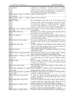
Aux. Input 3
Multiple function auxiliary input. These inputs are
activated if it is connected to battery negative. If this
input is used for auxiliary input. Alarm will be shown
as A3 in the display at the same time with auxiliary
led indication.
19
Aux. Input 4
Multiple function auxiliary input. These inputs are
activated if it is connected to battery negative. If this
input is used for auxiliary input. Alarm will be shown
as A4 in the display at the same time with auxiliary
led indication.
20
Oil Pressure
If oil sender that have both sender and switch function
is used, sender terminal must be connected to this
terminal. If oil sender that has single oil pressure
switch output, switch output must be connected to this
input. Suitable configuration must be set for this input
to use it as oil pressure switch or sender input.
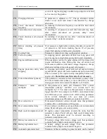
21
Temperature
If temperature sender that have both sender and
switch function is used, sender terminal must be
connected to this terminal. If temperature sender that
has single temperature switch output, switch output
must
be
connected
to
this
input.
Suitable
configuration must be set for this input to use it as
temperature switch or sender input.
22,23,24,25
HIGH
VOLTAGE
Mains
Line
and
Neutral Inputs
Mains line and neutral are connected to these
terminals.
26,27,28,29
HIGH
VOLTAGE
Generator Line and
Neutral Inputs
Generator line and neutral are connected to these
terminals.
30,31,32,33
34, 35
Current Transformer
Inputs
Secondary side of current transformer must be
connected here. Each transformer must be connected
separately.
Note: Battery negative must be connected to earth
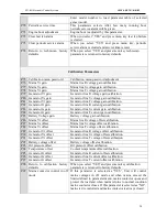
RUNNING MODES
Automatic Mode:
If you press automatic button marked “A” genset will switch to automatic
mode. In this mode panel controls mains voltages and if mains is outside the limits that you
programmed, Panel will open the mains contactor and starts the genset. After “engine
stabilization time” and “generator contactor delay” load transferred to the generator. Panel
controls all the engine values to detect possible failures after engine stabilization time. If
mains come to normal condition, mains is controlled during “mains return delay” for
stabilization. If mains is normal “after mains return delay”, generator contactor opens and
mains contactor closes. Genset is stopped after cooling period. In automatic mode, if panel is
in engine off state and detects an engine running signal. Panel will stop the engine.
Test Mode:
If you press test button at the right side of front panel. Genset will be switched to
test mode. In test mode engine starts immediately. After “engine stabilization time” if
parameter”test mode” is test off load genset wait for mains failure in running condition. When
mains failure occur mains contactor opens and generator contactor closes. In same way when
mains returns, panel waits”mains return delay” and switch back to mains. If parameter “test
mode” is test on load. After engine starting, generator contactor closes and genset supply the


