1
TRANSFERRING THE PARAMETERS
Parameter Transfer from Device to ENDAKEY-RF.
Parameter Transfer from ENDAKEY-RF to Device.
By pressing the key for 6 seconds continuously,
Hrd
message appears and the device waits for reading ENDAKEY-RF.
By touching with the ENDAKEY-RF to top of the left corner of the device and by pressing to button on the ENDAKEY-RF,
parameters will be transferred to the ENDAKEY-RF. If the parameter transfer is successful,
5uc
message appears on the
display.
By touching with the ENDAKEY to top of the left corner of the device and by pressing to button on the ENDAKEY,
parameters will be transferred to the device. If the parameters transferred successfully,
HYE
and
5uc
message appears on
display.
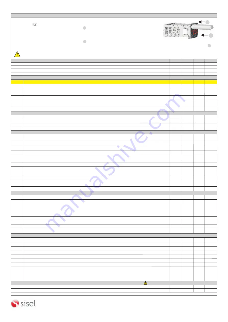
Move
ENDAKEY-RF
towards the
top left of the device in direction
1
CONTROL PARAMETERS
R1
R2
-
60.0
150.0
°C
150
-60.0
150.0
°C
-
60
R0
o1
20.0
°C
2
20.0
°C
0
0.1
-
20.0
MIN.
MAX.
UNIT
DEF. SET
°F
°C
C0
C2
C4
99
:
00
min:sec
99
:
00
min:sec
0
:
00
99
:
00
min:sec
°C
0
:
00
0
:
00
0
:
00
P1
No
YE5
No
CONFIGURATION PARAMETERS
COMPRESSOR PROTECTION PARAMETERS
DEFROST CONTROL PARAMETERS
Delay time required for the compressor to restart following a stop.
i5
Digital input types.
nd
:Digital input unused.
EA
: External alarm.
EA
message flashes in the display. Output unchanged.
5
A
:Important external alarm.
5
A
message flashes in the display.Relay output is turned off.
df
:
Defrost operation is started.
i3
Digital input delay. The period of the digital inputs to be active.
99
:
00
nd
dF
nd
Upper limit for setpoint value.
Lower limit for setpoint value.
Cooling hysteresis.
Offset value for cooling.
Decimal point (
no
= decimal point not added, ie
22
°
C,
YE5
=decimal point added, ie
22.3
°
C.)
Delay time for the compressor after power is on.
Off time for the compressor output in the case of probe failure
Digital input polarity.
cL
=
While a digital input contact is closed,it is activated.
oP
=
While a digital input is opened, it is activated.
CL
oP
Cl
1
:
00
1
:
00
1
:
00
0
:
00
0
:
00
(Devices with part code suffix ‘F' have deg F as the default 'Unit').
LP
While keylock active, the set value is changed.
NO:
Set value is not changed.
YE5:
Set value is changed.
no
yE5
no
i1
- Please specify at order “ENDAKEY-RF” if required.
Defros type selection (
ELC
: electric defrost (compressor is switched off),
GA5
: hot gas (compressor is ON))
1
1
1
SİSEL MÜHENDİSLİK ELEKTRONİK SAN. VE TİC. A.Ş.
Şerifali Mah.
Y.Dudullu 34775
ÜMRANİYE/İSTANBUL-TURKEY
Tel : +90 216 499 46 64 Pbx. Fax : +90 216 365 74 01
url : www.enda.com.tr
Barbaros Cad. No:18
3
/4
P2
Temperature unit
0
:
00
99
:
00
min:sec
C5
On time for the compressor output in the case of probe failure.
d4
YE5
No
No
d3
99
:
00
min:sec
0
:
00
Defrost duration (If
d.dur
=
0
, automatic and manual defrost will be disabled.)
Defrosting process begins with energy (
no
=
Defrost process doesn’t start when the energy comes.
YE5
=
Defrost process starts when the energy comes.)
1
:
00
d1
ELC
GA5 ELC
d2
-600 150.0 2.0
Defrost stop temperature ( If evaporator temperature is greater than this value, defrost will not work)
°C
d9
d5
99
:
00
99
:
00
min:sec
d6
rE
Lc.
Lc.
0
:
00
1
:
00
During defrost,display configuration (
rE
=
Real temperature is displayed during defrost.
(
Lc
=
The temperature which is measured before defrost is displayed during defrost.
Delay time for defrosting after power is on.
Delay time for display real temperature after defrost is over.
1
:
00
min:sec
0
:
00
d7
99:00
0:00
Dripping (discharge) time
2:00
min:sec
A1
A4
A7
A3
A2
A4
°C
-60
A1
150.0
°C
150
0:00
99:00
0.1
20.0
°C
Ab5
rEF
Ab5
A6
99:00
min:sec
0:00
-60.0
0:00
Limit for upper alarm level. When
A2
is changed, it should be readjusted.
Limit for lower alarm level. When
A2
is changed, it should be readjusted.
Hysteresis alarm
Alarm configuration. (
Ab5
= Independent alarm. Alarm values are
A1
and
A4
.)
(
rEF
= Relative alarm. Alarm values are
SET-A1
and
SET+A2
.)
NOTE: Upper and Lower alarm level variables are determined according to the “
A.tYP
” parameter.
If
A1
=
A.b5
,
A1
and
A4
.
If
A2
=
rEF
,
R1
=
SET-A1
and
A4
.
Time delay to display alarm message after alarm is on.
Time delay to display alarm message after power is on.
2
0:10
hr:min
150.0
°C
/°F
1
no
YE5
YE
5
99
:
00
min:sec
3
:
00
2
no
YE5
YE5
99
:
00
min:sec
1
:
00
yE5
no
0.1
20
.
0
°C
/
°
F
-
60.0
00
:
00
00
:
00
no
Fan control depending on room temperature. (
no
=
If evaporator temperature over
f5tp
value, fan does not run.
y
E5
=
If difference between room temperature and the temperature of the evaporator temperature is below from
f.5tp
value, fan stops. If the room temperature and evaporator temperature differences greater than
f5tp
+
f.hy5
,
fan runs again.
Fan operates with thermostat .(
no
=Fan runs independently from thermostat.,
y
E5
=Fan operated with thermostat.
Fan operation during defrost process.(
no
=
,
y
E5
= Fan stops during defrost process.)
Fan holds its status
Required delay time for fan to be powered up.
Required delay time for fan to be powered up after defrost.
FAN CONTROL PARAMETERS
Fan stop temperature.
F1
F6
F3
F0
F4
F2
F7
H2
H1
19.20
1
off
Modbus slave device address for device
MODBUS COMMUNICATION PARAMETERS
Modbus communication speed ( Baud rate, 0 :
oFF
, 1 :
1200
, 2 :
2400
, 3 :
4800
, 4 :
9600
, 5 :
19.20
)
247
1
bps
9600
Please see page 2 for Modbus Connection Diagram.
d8
Smart Defrost selection (
no
: Defrost counter (between 2 defrost duration) decrease irrespective of status of the compressor.
YE5 :
Defrost counter decreases as long as compressor work
.
).
No
YE5
No
d0
The time between 2 consecutive defrosts.
1
:
00
99
:
00
hr:min
1
:
00
ALARM CONTROL PARAMETERS
Fan differential.
F5
Fan operations when compressor stop. (
no
= Fan holds its status,
y
E5
= Fan stops with compressor.)
no
YE5
YE5


