EDM01-07: DAG 3.7G Card User Guide
Version 7: May 2006
26
©2005
Generic
Header
(cont.)
flags
This byte is divided into several fields as follows:
1-0:
Enumerates capture interface 0-3
2:
Varying record lengths
3:
Truncated record (insufficient buffer space)
4:
RX error (link layer error)
5:
DS error (internal error)
6:
Reserved
7:
General direction bit. This bit has two uses, it indicates
from where a packet has arrived, either the host or line,
and enables the XScale to target the packet at either the
host or line. The direction bit can be interpreted in the
context of either the Rx or Tx hole
In the XScale/Host Rx hole, a value of “
1
” indicates the
ERF has arrived from the line. A value of “
0
” indicates
the record was received from the host.
In the XScale Tx hole, a value of “
1
” tells the ERF
Mux to direct packets to the line. A value of “0” directs
packets to the host.
rlen
Record length. Total length of the record transferred over the
PCI bus to storage.
lctr
Depending upon the ERF type this 16 bit field is either a loss
counter of colour field. The loss counter records the number of
packets lost between the DAG card and the memory hole due to
overloading on the PCI bus.
wlen
Wire length. Packet length including some protocol overhead.
The exact interpretation of this quantity depends on physical
medium.
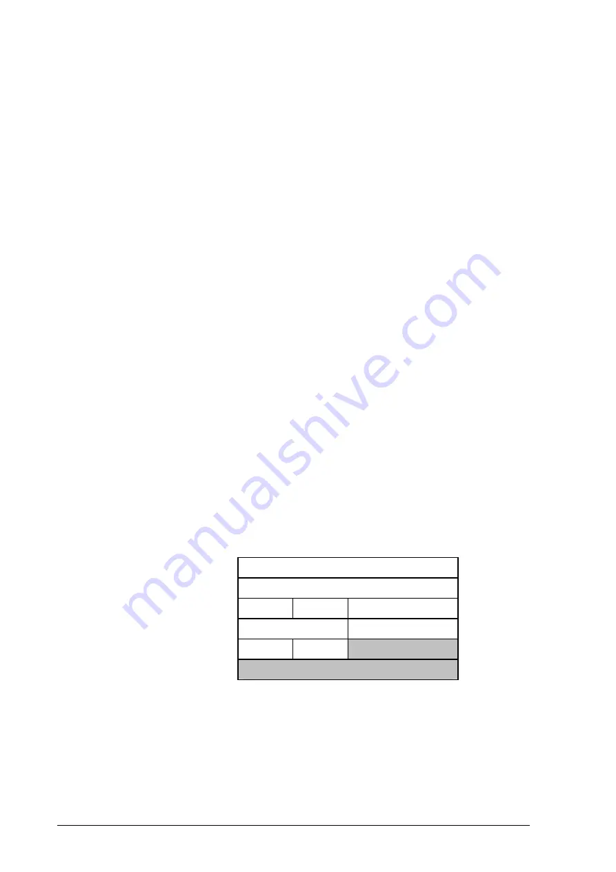
Type 2 Record
The Type 2 Ethernet record is shown below:
timestamp
timestamp
type:2
flags
rlen
lctr
wlen
offset
pad
rlen-18
bytes of frame
The Ethernet frame begins immediately after the pad byte so that the layer 3
[IP] header is 32Bit-aligned
Summary of Contents for DAG 3.7G Series
Page 1: ......
Page 4: ...EDM01 07 DAG 3 7G Card User Guide Version 7 May 2006 2005...
Page 18: ...EDM01 07 DAG 3 7G Card User Guide Version 7 May 2006 12 2005...
Page 30: ...EDM01 07 DAG 3 7G Card User Guide Version 7 May 2006 24 2005...
Page 34: ...EDM01 07 DAG 3 7G Card User Guide Version 7 May 2006 28 2005...


