Endace Measurement Systems Limited
http://www.endace.com
EDM01.05-12r1 DAG 3.7T Card User Manual
Copyright, all rights reserved.
8
Version 6. 22 September 2005.
3.2 DAG 3.7T Card LED Display Functions
Description
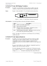
The DAG 3.7T LED display functions indicate a number of process
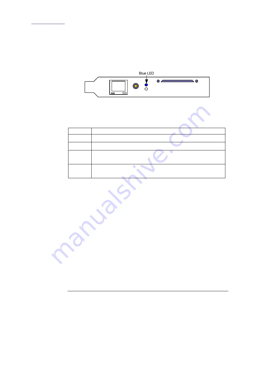
conditions. When the card is powered the blue LED 1 should be lit.
Figure
Figure 3-2 shows the DAG 3.7T card without network connections.
Figure 3-2. DAG 3.7T Card without Network Connections.
LED definitions
The following table describes the LED display definitions:
LED Description
FPGA successfully programmed
LED 1
LED 2 Data capture in progress
LED 3 PPS Out: Pulse Per Second Out – indicates the card is
sending a clock synchronization signal
LED 4 PPS In: Pulse Per Second In – indicates the card is receiving
an external clock synchronization signal
NOTE: The LED 4 is on when the Loss of Pointer or Loss of Framing
conditions are true.
3.3 DAG 3.7T Card Capture Sessions
Description
The DAG 3.7T uses two integrated Exar Octal T1/E1 Framers which
enable support for both T1 and E1 interfaces. They also enable soft
configuration of the line termination and gain, and physical layer
configuration such as the selection of B8ZS or AMI zero code suppression
options.
Because of its flexibility, the correct link layer configuration needs to be
supplied to the card to function as expected.
For both configuration and statistics of the DAG 3.7T framers the
dagthree
tool is supplied. Calling
dagthree
without arguments will list the current
settings.
dagthree -h
will print a help listing on the usage of the tool.
Continued on next page


