Endace Measurement Systems Limited
http://www.endace.com
EDM01.05-12r1 DAG 3.7T Card User Manual
Copyright, all rights reserved.
9
Version 6. 22 September 2005.
3.3 DAG 3.7T Card Capture Sessions
, continued
Procedure
Follow these steps for the DAG 3.7T card capture session.
Step 1.
Connect Pod
Connect the Pod to the DAG 3.7T using the supplied 68-pin VHDCI
connector.
Step 2.
Connect Integrated Exar Octal T1/E1 Framers
Using a correctly wired connector, connect the T1 or E1 line to an RJ45
socket on the Pod.
NOTE: Up to 16 lines can be connected.
Step 3
Check FPGA Images
Before starting to configure the card, make sure the most recent pair of
FPGA images has been loaded onto the card. Load the newest available
PCI FPGA image.
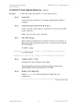
For HDLC capture:
dag@endace:~$ dagrom -rvp –d dag0 -f xilinx/dag37tpci-hdlc-erf.bit
For ATM capture:
dag@endace:~$ dagrom -rvp –d dag0 -f xilinx/dag37tpci-atm-erf.bit
Step 4.
Configure DAG 3.7T Card
Configure the card according to local settings.
Check through the physical layer statistics that the card has frame
synchronization and is locked to the T1 or E1 links.
Step 5.
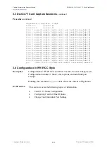
Display Card Configuration
Run the
dagthree
tool without arguments to display the card
configuration.
Continued on next page

