background image

Endevco Model 123 

3-Channel

PE/IEPE Signal Conditioner 

INSTRUCTION 

MANUAL

IM123


Revision A2


October 28, 2013


Summary of Contents for 123

Page 1: ...Endevco Model 123 3 Channel PE IEPE Signal Conditioner INSTRUCTION MANUAL IM123 Revision A2 October 28 2013 ...

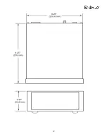
Page 2: ...formation 5 Front Panel 6 Rear Panel 7 Setting Up the Model 123 8 Calculating Setting Gain 8 Filter Module Installation 10 Signal Ground Power Ground Isolation 11 Included Optional Accessories 11 Outline Dimensions 12 Table of Contents ...

Page 3: ...hazard may be present Read the instruction manual carefully and insure that the device is wired properly and that all settings have been checked prior to applying power to the device The WARNING label indicates important information that should be heeded for safe and proper performance of the device The CAUTION label is used to indicate that damage to the power supply or equipment connected to it ...

Page 4: ...e with minimum self generated noise and provides clean clock free amplified signals The Model 123 also uses low noise linear voltage regulators instead of switching regulators to minimize interference The Model 123 uses 12 bit DACs for each channel to set amplifier gains from 0 00 to 999 9 with 0 5 precision Amplifier gains can be changed on the fly without damage to the instrument The Model 123 p...

Page 5: ...t voltage Connect inputs and outputs prior to applying power to the instrument For connection to PE sensors set INPUT SELECT switch to PE position and connect to the BNC input for PE sensors For connection to IEPE sensors set INPUT SELECT switch to IEPE position and connect to the BNC input for IEPE sensors Select 4mA or 10mA source current for IEPE sensor excitation CH1 CH2 and CH3 Signal Outputs...

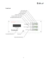
Page 6: ...6 Front Panel ...

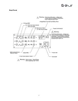
Page 7: ...7 Rear Panel ...

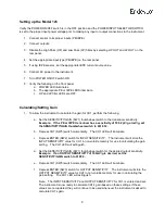
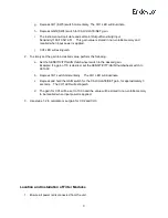
Page 8: ...ple If the PE or IEPE transducer has a sensitivity of 10 52 pC g or mV g set the SENSITIVITY GAIN thumbwheel switch to 0010 52 b Depress CH1 SW5 switch momentarily The CH1 LED will illuminate c Depress ENTER SW2 switch for INPUT SENSITIVITY The instrument will store the INPUT SENSITIVITY value for CH1 in non volatile memory for use in calculating the gain setting The CH1 LED will extinguish d Set ...

Page 9: ...SENSITIVITY GAIN thumbwheel switch to the desired gain Example If a gain of 10 is desired set the SENSITIVITY GAIN thumbwheel switch to 0010 00 b Depress CH1 switch momentarily The CH1 LED will illuminate c Depress and hold the GAIN switch for the CALCULATE SET gain for approximately 3 seconds The CH1 LED will extinguish d The gain for CH1 will be set to 10 00 and the value will be stored in non v...

Page 10: ... see filter sockets as indicated below 6 places Each socket is labeled on the board with the channel number and LP HP 4 Install filter module like shown below shown with LP Filter Module installed 5 Filter modules for both LP and HP filters on all channels are installed in the same manner Signal Ground Power Ground Isolation ...

Page 11: ...tch set to the numbered side signal ground is isolated from power ground default pictured below for each channel With the switch in the alternate position signal ground is shorted to power ground Included Optional Accessories Part Number Description EW599 Powercord Included IM123 Instruction manual Included EJ21 BNC to 10 32 adaptor Optional 31875 XXXX Y Low pass filter module Optional 42875 XXXX ...

Page 12: ...12 ...

Reviews: