ENDEVCO 2680
INSTRUCTION MANUAL
IM2680
Page 3-1
SECTION 3:
PRE-OPERATION TEST
1.
INTRODUCTION
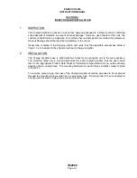
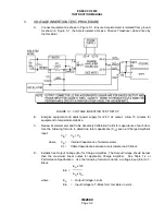
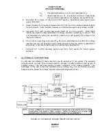
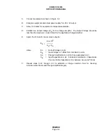
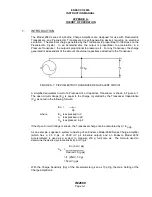
It is sometimes desirable (or required) to test the integrity of a system after installation. A
suggested method for performing a pre-operation test is the Voltage Insertion Test. Ideally, a
Voltage Insertion Test performed in a calibration laboratory can be used to establish normal
response of the system. The test is not only useful to check the Accelerometer/Cable/Amplifier
Circuit Continuity, but can also be considered a Calibration Test. If the Accelerometer has an
open circuit, the Charge Amplifier's output signal will be less than normal since only the cable
capacitance remains in the input circuit. If the accelerometer is shorted, the Charge Amplifier's
output will be zero. If a short circuit exists in the Charge Amplifier, the output again will be zero, or
considerably lower than normal.
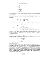
Since the Voltage Insertion Test requires using formulas to obtain data, certain parameters of
system components must be known, or established, prior to performing the test. The internal
capacitance of the Accelerometer and the capacitance of the cable must be known. These values
are obtained from the calibration card shipped with each item. Also, the Charge Amplifier's output
voltage must be established. The output voltage established must be less than the Charge
Amplifier's full-scale output (maximum 5 V p-p, or 1.77 V rms). As an example, the 2680M1 has a
maximum linear biased output of 4.65 V p-p (1.64 V rms) into a 10,000-ohm load. Thus, the
output established for a 2680M1 should be less than 4.64 V p-p. Normally, an output voltage is
selected which is easily read on the readout device. For example, if an oscilloscope is being
used, an output voltage should be selected to provide a full-scale output easily determined by
viewing the oscilloscope grid (graticule).
When performing the Voltage Insertion Test, the Accelerometer must be isolated from ground.
Total source capacitance should not be more than 10,000 pF for the Charge Amplifier to meet all
specifications.
2.
EQUIPMENT REQUIRED
The following equipment is required to perform a Voltage Insertion Test:
A.
Oscillator capable of operating over the minimum range of 3 Hz to 20 kHz.
B.
Power supply, +20 to +32 V dc rated at 50 mA maximum.
C.
T-
Block containing a 100 Ω, 1/2
-
watt, ±0.5% resistor.
Endevco T-Junction Calibrator, part number 2944.1 is recommended.
D.
Oscilloscope to verify Oscillator and Charge Amplifier Outputs.
E.
Digital voltmeter (DVM) to monitor Oscillator and Charge Amplifier Outputs in AC volts, or V
rms.
F.
Accelerometer isolated mounting studs. Endevco Model 2980 Series isolated Mounting
Stud is recommended. Stud is used to isolate Accelerometer from ground.
G.
Switch, SPDT (S1)
H.
Switch, DPDT (S2)

