ENDEVCO 2680
INSTRUCTION MANUAL
IM2680
Page 4-1
SECTION 4:
OPERATIONAL CHECKOUT PROCEDURE
1.
USING THE CHARGE AMPLIFIER
The 2680 series of Charge Amplifiers are designed to operate with Piezoelectric Accelerometers
and other Transducers. In all cases the Transducer and Connecting Cable must form the
equivalent of a capacitive input device. Total source capacitance for the input should not be more
than 10,000 pF, or as specified on the Product Data Sheet, or Performance Specification.
A simple block diagram of a system using the Charge Amplifier is shown in Figure 4-1. To
prevent ground loops and excessive noise, the Transducer should be mounted on an insulated
stud. The Charge Amplifier case should also be grounded somewhere in the system to prevent
stray pickup. Coaxial cable is to be used between Transducer and Charge Amplifier. The
sensitivity of this system is not appreciably affected by the cable capacity.
Readout devices such as Oscilloscopes, Oscillographs (for hard-copy print-outs), Digital
Voltmeters, etc., can be used to analyze the Shock and Vibration Data. These instruments are
selected according to user preference and requirements.
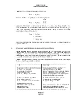
At 1000 Hz, the biased and unbiased outputs of the M1 through M7 series of Charge Amplifiers
(2680M1 through 2680M7, 2681M1 through 2681M7, etc.) are in phase with the input. The 1-10
mV/pC low -gain outputs of the M12 and M14 are in phase with the input signal, while the 10-100
mV/pC high-gain outputs of the M12 and M14 are 180° out-of-phase with the input.
2.
GAIN ADJUSTMENT
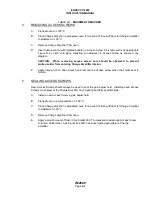
Each Charge Amplifier provides two outputs, and Gain Potentiometer is common to both outputs.
Those Charge Amplifiers (M12 and M14) with dual biased or dual unbiased outputs have a 10:1
ratio maintained between both outputs by the common Gain Potentiometer.
A.
Connect equipment per Figure 4-1. Ensure J2 pin assignments conform to Charge
Amplifier being tested. See Note in Figure 4-1.
B.
Energize equipment and allow 15 minutes to temperature stabilize.
C.
Adjust power supply for +28 V dc output.
D.
Adjust Oscillator Frequency to 100 Hz and an Output Amplitude of 50 mV rms.
E.
Set Voltage Divider Potentiometer to its maximum output (fully CW).
F.
Set test setup switch S1 to OUT position.
NOTE: A Charge Amplifier's Gain is not electrically continuous at extreme ends of the
Gain Potentiometer. The output could be erratic (minimal, or no change) at both ends.
G.
Adjust Charge Amplifier's Gain Potentiometer through its complete range and monitor DVM
for change in Charge Amplifier's output. Each "M" series Charge Amplifier's output should
vary according to limits listed in Adjustable Gain Range column in Table 1-2, or as specified
in Performance Specification.
H.
Remove test setup lead from Charge Amplifier's connector pin J2-C and connect to J2-B.
Repeat step G for Charge Amplifier's second output.

