ENDEVCO 2680
INSTRUCTION MANUAL
IM2680
Page 1-1
SECTION 1:
DESCRIPTION
1.
INTRODUCTION
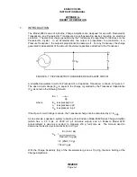
The Endevco® Model 2680 Series of Charge Amplifiers are Solid-State Airborne Devices
designed for use with Piezoelectric Transducers. The Charge Amplifiers are epoxy-potted and
hermetically sealed units containing a charge converter front end to receive the transducer signal,
an optional filter to select the flat frequency response of the charge amplifier, a gain potentiometer
to set the desired gain of the charge amplifier, and a voltage amplifier in the output. The charge
amplifier produces an output voltage proportional to the charge at the input, thus minimizing the
effect of input cable length. The charge amplifier uses hybrid microcircuits to achieve small size,
low weight, and low power consumption.
The case of each charge amplifier is completely isolated from the circuit, and an internal
electrostatic shield protects from stray pickup. A DC-to-DC Converter installed in specific models
isolates power and signal grounds.
The series of charge amplifiers covered by this instruction manual are listed below with a brief
description defining each configuration. As noted the difference between the basic charge
converter Models (2680 & 2681) is the type of output connectors used and the addition of the DC-
to-DC Converter. Table 1-1 provides a further breakdown between the basic models.
Basic Model Configuration
2680
Viking Connector
2681
Viking Connector, DC-to-DC Converter
2685
Endevco Connector, DC-to-DC Converter
Integral Electronic Conditioner with constant current supply
Each basic model consists of a series of modifications ("M series) to provide seven different gain
ranges and nine different high frequency responses. The "M" series covered by this Instruction
Manual are M1 thru M7, M12 and M14. Table 1-2 lists the "M" series and provides a comparison
of their input and output characteristics.
2.
ADJUSTABLE GAIN
The Charge Amplifier's case contains a removable screw to permit access to a Gain
Potentiometer. The Potentiometer enables the user to adjust the gain to any desire setting within
the gain range of the Charge Amplifier.
The Gain-Access Screw is located on the side of the case for Charge Amplifiers without DC-to-DC
Converters, and on the connector end of the case for Charge Amplifiers with DC-to-DC
Converters. Refer to Table 1-1 for the basic model numbers of Charge Amplifiers containing the
DC-to-DC Converters, and to Figures B-2 and B-3 for location of the Gain Adjustment.
The Gain Adjustment is a 12-
turn (typical), 500 kΩ (±0,1%) Potentiometer with wiper idles as
mechanical stops at the extreme clockwise (CW) and counterclockwise (CCW) positions.
Maximum resistance (minimum Charge Amplifier Gain) is obtained in the extreme CW position.
Signals are present at both ends of the Potentiometer, but signal changes may not occur during
the final two turns.
Charge Amplifiers shipped as a component of an Endevco system (Accelerometer, Cable
Assembly and Charge Amplifier) normally have the gain factory-set to a specific gain, and the
Gain-Access Screw Solder-Sealed to the case of the Charge Amplifier. The Gain-Access Screw

