ENDEVCO
www.endevco.com Tel: +1 (866) ENDEVCO [+1 (866) 363-3826]
IM 2680/5 083119
20
6.14
2685 quick test
Equipment required:
•
Digital storage oscilloscope
•
Digital multimeter
•
28 VDC power supply with an output mA meter
1
Apply 28 Volts between pins A (+) and D. and confirm that the
current is within the specifications in table 4.
2
Connect a 10k Ω (minimum) resistor between pins C and D.
3
With a DMM, measure the DC voltage across the 10k Ω resistor. The
voltage should read 2.50 VDC ±3%.
4
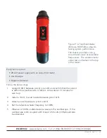
Connect an IEPE accelerometer to the 10-32 input connector.
5
Connect an oscilloscope to either/or Pins B and D or C&D. AC
coupling is recommended if using pins C&D.
6
Tap the base of the accelerometer with a wooden pencil, or a plastic
screwdriver handle.
7
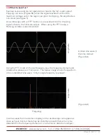
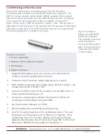
Look for an output response on the oscilloscope screen. Figure 11 is
an example of a response from a hard strike.
8
If a response is observed on the oscilloscope, the test is complete.
9
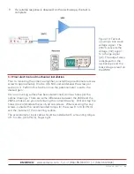
Install the accelerometer cable in such a way that the DC voltage
can be measured. This is best accomplished using a pair of 10-
32 to BNC cables (Endevco 3061) joined by a BNC “T” connector
(Amphenol 112461, or equiv.) per figure 5.
10
Refer to the accelerometer’s calibration certificate and note the bias
Voltage.
11
With the power applied (28 VDC), measure the transducer’s bias
voltage as shown in figure 12. It should read approximately the
same as the bias voltage recorded on the calibration certificate.
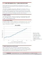
Note that the ambient temperature affects the transducer’s bias
voltage level. The calibration temperature is recorded on the
certificate.
Figure 12: A “T”
connector can be used
between two BNC to
10-32 cables allowing
for the measurement
of the bias voltage at
the male center of the
connector
To DMM
To accelerometer
BNC “T” CONNECTOR
To 2685


