ENDEVCO
www.endevco.com Tel: +1 (866) ENDEVCO [+1 (866) 363-3826]
IM 2680/5 083119
21
6.2
2680 Testing without the sensor
Testing with high accuracy is possible using common laboratory
instruments and an Endevco model 2947C Calibration Capacitor. The
2947C is simply a stable, well-shielded 1000pF capacitor that is placed
between the signal generator and the 2680 charge amplifier. Its purpose
is to convert the signal generators output voltage to a charge (pF)
signal. When using a 1000 pF capacitor, charge = volts. The accuracy is
dependent on the tolerance of the capacitor and the accuracy of the signal
generators output level. The 2947C’s internal capacitor is measured and
the actual capacitance is marked on the case.
Equipment required:
•
Function generator
•
Endevco 2947 Calibration capacitor
•
Oscilloscope
•
Digital multimeter
1
Apply 28 Volts between pins A (+) and D. and confirm that the
current is within the specifications in table 4.
2
Connect a 10k Ω (minimum) resistor between pins C and D.
3
With a DMM, measure the DC voltage across the 10k Ω resistor. The
voltage should read 2.50 VDC ±3%.
4
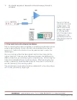
Connect the 2947C to the 10-32 connector and the BNC end to a
function generator (see figure 14).
5
Connect an oscilloscope to either/or Pins B and D or C&D. AC
coupling is recommended if using pins C&D.
6
Set the sine wave frequency to 100 Hz.
7
Set the amplitude to a level that will produce 10 g.
8
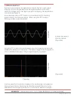
Look for an output response on the oscilloscope screen. The user
should see a pure sine wave with no distortion or clipping. If the
oscilloscope has an FFT function, observe the frequency domain
response that should be free of harmonics (Figure 4B). Confirm that
there are no 50Hz/60 Hz lines present in the spectrum.
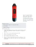
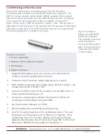
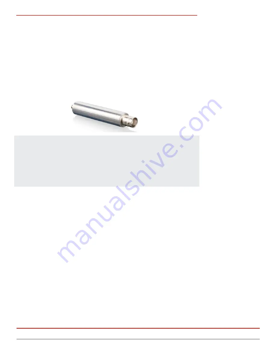
Figure 13 shows an
Endevco model 2947C
calibration capacitor.
The capacitor is housed
within a shielded
environmentally sealed
case. The capacitance is
measured and marked
on the housing.


