ENDEVCO
www.endevco.com Tel: +1 (866) ENDEVCO [+1 (866) 363-3826]
IM 2680/5 083119
22
9
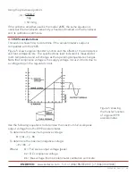
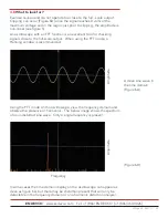
If a suitable response is observed on the oscilloscope, the test is
complete.
6.3
Final electrical and mechanical installation
Prior to mounting the airborne amplifier, reinstall the potentiometer access
screw to approximately 8 in-lbs. (0.6 Nm) and solder-seal the screw per
section 3.3. Perform this function once the potentiometer is set to the
desired gain.
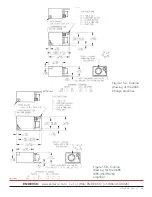
Once a mounting surface has been determined, drill two holes per the
outline drawings. There are some differences between the 2680 and the
2685 so make sure you are following the correct drawing. Drill and tap the
holes to accommodate the two 6-32 cap screws. When securing the cap
screws, consider the recommended torque for the screw 8 in-lb (0.9 Nm)
and the material of the mounting surface.
The accelerometer input cable should be installed with a mounting torque
of 1.5 in-lbs. (0.169 Nm), finger tight.
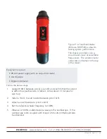
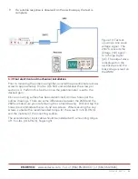
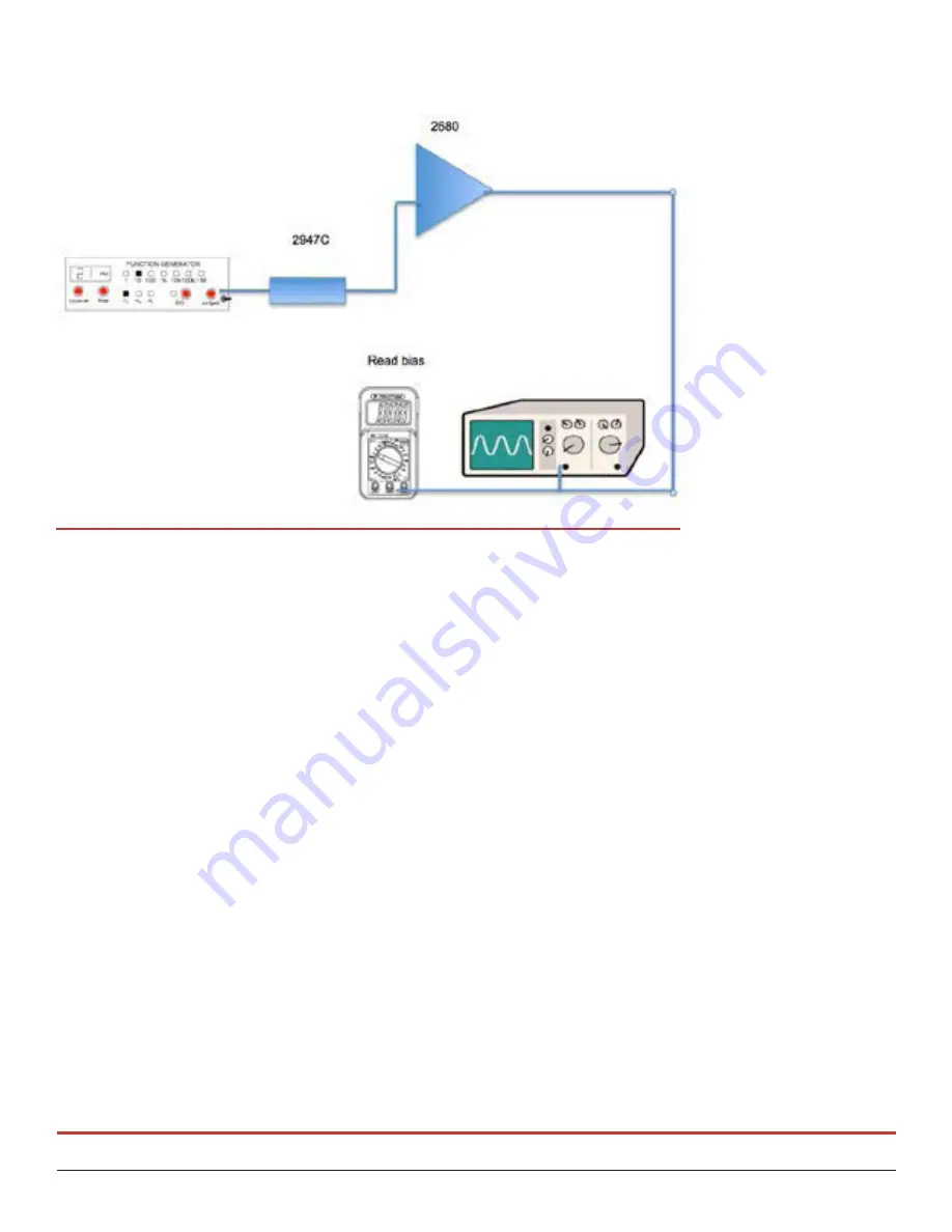
Figure 14: Test set-
up using a sine wave
voltage signal. The
2947C converts the
voltage (mV) signal
to a charge signal
(pC). The output wave
is displayed on the
oscilloscope and the
bias voltage is read on
the DMM.

