ENDEVCO
www.endevco.com Tel: +1 (866) ENDEVCO [+1 (866) 363-3826]
IM 2680/5 083119
9
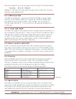
Maximum output voltage is approximately 0 to 5 v (± v pk) depending on
the specific airborne amplifier. The output circuits are short-circuit proof,
thus the outputs will withstand an indefinite short without damage.
4.4.1
Biased output
The biased output is available from pin C (+) and pin D (ground). This
output is
direct-coupled with an output impedance of less than 50 ohms. With
no input, the airborne amplifier pr2.5 v dc, ±3% at the output.
Output voltage will be approxi/- 2.5 V pk around this bias level.
Clipping will occur slightly above the O V level and b5.0 and
+5.3 V.
4.4.2
Unbiased output
The unbiased output is available between pins B (+) and D (ground).
This output is taken from the same source as the biased except a series
decoupling capacitor blocks the DC bias only allowing only the AC
signal to be available at pin B. With the addition of the series capacitor
and bleed resistor in the output, a 0.00 V bias level is established. The
unbiased output is linear from 0 to 4.65 V p-p, or 0 to 5.00 V p-p,
depending on the specific airborne amplifier used.
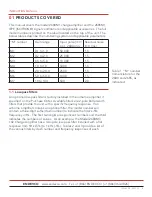
Refer to Table 1-2 for further output data on specific airborne amplifiers.
4.5
Adjustable gain
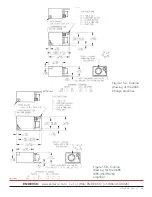
The airborne amplifier’s enclosure contains a removable screw to permit
access to a gain potentiometer. The potentiometer enables the user
to adjust the gain to any desired setting within the gain range of the
amplifier. For example, in an M3 version; the gain range would be 0.5 to
5 per table 1. The gain-access screw is located on the side of the case
as shown in figure 4. Remove the access screw using a 5/64” hex wrench
with an insulated handle.
Figure 4 illustrates
removal, re-installation
and solder sealing of
the gain adjustment
potentiometer A
200-watt soldering iron
with a narrow tip is
recommended

