background image

DOCUMENT EDVIM4418 REVISION B 

Page 6 of 14 

3.1 Transducer 

Connection 

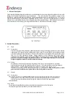
The transducer is connected to the 5 pin input socket.  A high accuracy voltage reference source 
provides power to the transducer.  When powered, the transducer will set a voltage at the inputs of 
the 4418 of approximately 5VDC


(dependent on the transducer and the offset).  The 4418 monitors 

this voltage to be within a pre-set range.  If the voltage is within the range the status indicator is 
turned Green and the system is ready to use.  If the voltage is out of range, the status indicator is 
turned Red – a fault condition exists.  

Note: Some transducers can take 1 – 2 minutes before 

the voltage settles into range. 

 Fig 

3. 

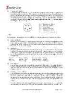
Pin Connections - as viewed from the front of the 4418 or the rear (wire side) of the mating input plug. 

3.2 Output 

Connection 

Measuring Instrumentation, e.g. data acquisition, data logger etc. should be connected to the output 
socket using coaxial cables.  Load impedance should be no lower than 100k

 to meet all 

specifications.  Ideally, the 4418 should be placed near the measuring instrumentation to minimize 
the effect of cable capacitance loading. 

3.3 Gain 

Setting 

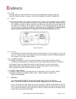
Depressing the “Gain” switch cycles through the gain ranges of  x1, x10 and x100.  The gain range 
selected is shown by the indicator above the range being lit.  The gain together with the transducer 
sensitivity determines the acceleration range available from the system and the output sensitivity, 
e.g. for an accelerometer having a sensitivity of 10mV/g pk, and the maximum output of the 4418
being 10V pk:

Gain = 1 

Range = 1000g 

Output sensitivity = 10mV/g 

Gain = 10 

Range = 100g 

Output sensitivity = 100mV/g 

Gain = 100 

Range = 10g 

Output sensitivity = 1000mV/g 

3.4 Filter 

Selection 

A second order low pass filter is selected by depressing the filter switch.  This toggles the filter in 
and out.  With the indicator lit, the filter is selected IN.  The Standard filter provides attenuation of   
-3dB at 10 kHz. The filter maybe used to reduce the effects of HF noise and aliasing in data
acquisition systems.

3.5 

The Bridge Balance (Offset) 
The control, located on the rear panel, provides a means of adjusting the unbalanced output of the 
transducer for a zero measured output of the signal conditioner.  To adjust the Bridge Balance, first 
place the transducer in an axis which is not the primary sensitive axis, i.e. at 90 degrees. Monitor 
the output of the signal conditioner with a dc voltmeter.  With the power turned ON and after the 
recommended stabilization time, adjust the control for as close to zero volts as possible at the 
output.   

The 4418 utilizes low drift components in the design. However, small changes may be required after 
the initial setting.  When using the x100 gain, the adjustment of the control is very sensitive.  It is,  

Pin 1 – Excitation 

-

ve  (

Black

Pin 2 – Signal 

-

ve  (

White

Pin 3 – 

Cable Shield*


Pin 4 – Signal 

+

ve  (

Green

Pin 5 – Excitation 

+ve

  (

Red

*Pin 3 is connected to output signal ground.

Summary of Contents for 4418

Page 1: ...DOCUMENT EDVIM4418 REVISION B Page 1 of 14 Instruction Manual 4418 Bridge Signal Conditioner ...

Page 2: ...e at his own expense In order to maintain compliance with FCC regulations shielded cables must be used with this equipment Operation with non approved equipment or unshielded cables is likely to result in interference to radio television reception This equipment is not designed to be used in potentially explosive environments It should not be used in the presence of flammable liquids or gases This...

Page 3: ...r 5 2 3 3 Battery Charge Indicator 5 3 Operation 3 1 Transducer Connection 6 3 2 Output Connection 6 3 3 Gain Setting 6 3 4 Filter Selection 6 3 5 ZMO Adjustment 7 3 6 Battery Charging 7 4 Maintenance Calibration and Repair 4 1 4 1 1 Equipment Required 8 4 1 2 Preliminary Instructions 8 4 1 3 Check Procedure 9 4 2 Repair 9 4 3 Battery Replacement 9 5 Frequency Response Curves Gain 1 11 Gain 10 12 ...

Page 4: ...m of a 10 VDC Excitation voltage Bridge balance or Zero Measure and Output ZMO adjustment is provided by means of a control Offset mounted on the rear panel Note No internal provision is made for bridge completion resistors If a half bridge transducer is to be used bridge completion resistors must be added externally 2 1 2 Status An indicator on the front panel shows the status of the input if a t...

Page 5: ...ators in turn and the filter indicator 2 3 2 Low Battery Indicator The battery Low indicator is on the front panel and will be lit Red when the battery reaches a pre determined discharge level At this point it is recommended that the charger be connected If the charger is not connected at this point the unit will continue to function until a second predetermined battery discharge level is reached ...

Page 6: ...termines the acceleration range available from the system and the output sensitivity e g for an accelerometer having a sensitivity of 10mV g pk and the maximum output of the 4418 being 10V pk Gain 1 Range 1000g Output sensitivity 10mV g Gain 10 Range 100g Output sensitivity 100mV g Gain 100 Range 10g Output sensitivity 1000mV g 3 4 Filter Selection A second order low pass filter is selected by dep...

Page 7: ...utomatically switch into Stage 2 Stage 2 Top Off Mode Top Off Mode will deliver sufficient charge to top up the battery to 100 of its capacity in approximately 45 minutes Once 100 capacity has been achieved the charge indicator will extinguish In the event of a fault with the battery charging circuit or the battery pack itself the charge indicator will be lit Red In this event please contact your ...

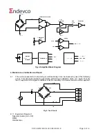
Page 8: ...g or malfunctioning it can be checked by use of the following circuit This circuit should also be used when performing a calibration of the unit Note To verify the LF response of the signal conditioner it will be necessary to increase the value of the capacitor Fig 5 Test Circuit 4 1 1 Equipment Required Signal Generator AC DC DMM Oscilloscope 5 2 3 4 1 ...

Page 9: ...ort circuit With the short circuit applied set the DMM to DC volts and with a gain of x1 adjust the bridge balance control Verify the output of the 4418 varies between 30mV to 30mV To verify the DC performance set the signal generator to DC volts and apply the same 50 mV dc level Note With the generator set to 0V adjust the bridge balance control for 0V at the output before applying the DC signal ...

Page 10: ...DOCUMENT EDVIM4418 REVISION B Page 10 of 14 This page is Left intentionally blank ...

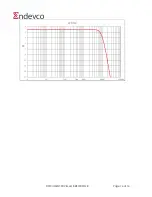
Page 11: ...DOCUMENT EDVIM4418 REVISION B Page 11 of 14 TYPICAL FREQUENCY RESPONSE CURVES ...

Page 12: ...DOCUMENT EDVIM4418 REVISION B Page 12 of 14 ...

Page 13: ...DOCUMENT EDVIM4418 REVISION B Page 13 of 14 ...

Page 14: ...DOCUMENT EDVIM4418 REVISION B Page 14 of 14 ...

Reviews: