background image

ENDEVCO MODEL 4990A RACK 

INSTRUCTION MANUAL 

TABLE OF CONTENTS 

1. INTRODUCTION....................................................................................................................................... 1 

1.1 SIGNAL CONDITIONERS .................................................................................................................... 1 
1.2 COMPUTER CONTROLLED SIGNAL CONDITIONERS ...................................................................... 1 
1.3 OASIS 2000 Hardware ......................................................................................................................... 1 
1.4 OASIS 2000 Software .......................................................................................................................... 2 

2. DESCRIPTION.......................................................................................................................................... 3 

2.1 KEY FEATURES .................................................................................................................................. 3 

3. FUNCTIONAL CHARACTERISTICS ......................................................................................................... 4 

3.1 General ................................................................................................................................................ 4 
3.2 Mechanical Characteristics ................................................................................................................... 4 
3.3 Model 4990A-1: Ethernet Option........................................................................................................... 4 
3.4 Model 4990A-2: RS-232 Option ............................................................................................................ 5 

4. INSTALLATION AND COMMUNICATION ................................................................................................. 6 

4.1 Unpacking ............................................................................................................................................ 6 
4.2 Installation ............................................................................................................................................ 6 
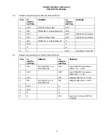
4.3 Default Jumper Settings for Ethernet Rack (4990A-1):.......................................................................... 9 
4.4 Default Jumper Settings for RS-232 Rack (4990A-2): ........................................................................... 9 

5. POWERING UP OF THE RACK ASSEMBLY AND ESTABLISHING COMMUNICATION........................ 10 

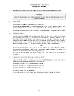
5.1 Apply Power ....................................................................................................................................... 10 
5.2 Computer Interface............................................................................................................................. 10 
5.3 Installing the OASIS SW2000 Software.  (Windows 95/98) ................................................................. 10 
5.4 Establishing Communication............................................................................................................... 11 

6. OPERATION ........................................................................................................................................... 19 

6.1 Connecting Sensors to OASIS 2000 ................................................................................................... 19 
6.2 Connecting the Analog Outputs .......................................................................................................... 22 

7. SAFETY .................................................................................................................................................. 23 

7.1 Ground The Instrument ...................................................................................................................... 23 
7.2 Do Not Operate In An Explosive Atmosphere ..................................................................................... 23 
7.3 Keep away from live circuits ............................................................................................................... 23 
7.4 Do Not Service Or Adjust Alone.......................................................................................................... 23 
7.5 Do Not Substitute Parts Or Modify Instrument .................................................................................... 23 
7.6 Dangerous Procedure Warnings ......................................................................................................... 23 
7.7 Safety Symbols .................................................................................................................................. 24 
7.8 Line Fuse ........................................................................................................................................... 24 
7.9 Troubleshooting Tips .......................................................................................................................... 25 

8. ROUTINE MAINTENANCE AND HANDLING .......................................................................................... 27 

8.1 Introduction ........................................................................................................................................ 27 
8.2 Factory Service .................................................................................................................................. 27 
8.3 WARRANTY....................................................................................................................................... 27 
8.4 OUT-OF-WARRANTY RETURNS ...................................................................................................... 27 

9. ORDERING INFORMATION & ACCESSORIES...................................................................................... 29 

9.1 OASIS Part Numbers ......................................................................................................................... 29 
9.2 Model 400 Series Accessories............................................................................................................ 29 

 

Summary of Contents for 4990A

Page 1: ...IM4990A REVISION A 30 July 2002 MODEL 4990A RACK FOR 400 SERIES AMPLIFIERS INSTRUCTION MANUAL E San Juan Capistrano California USA ...

Page 2: ...D ESTABLISHING COMMUNICATION 10 5 1 Apply Power 10 5 2 Computer Interface 10 5 3 Installing the OASIS SW2000 Software Windows 95 98 10 5 4 Establishing Communication 11 6 OPERATION 19 6 1 Connecting Sensors to OASIS 2000 19 6 2 Connecting the Analog Outputs 22 7 SAFETY 23 7 1 Ground The Instrument 23 7 2 Do Not Operate In An Explosive Atmosphere 23 7 3 Keep away from live circuits 23 7 4 Do Not Se...

Page 3: ... use of its sensors in large scale testing and to eliminate the risk of incorrect amplifier settings ENDEVCO has developed several generations of computer controlled signal conditioning systems The first generation was the Multi channel Amplifier Control system MAC The second generation was the Computer Controlled Amplifier Systems CCAS The CCAS family consists of five different systems that use t...

Page 4: ...lled in a Model 4990A rack The SW2000 software is a full featured software package designed to simplify system configuration and amplifier setup Intuitive simple to use graphical interface provides both table view and matrix view windows for quick configuration for up to 2048 channels Ethernet one or more 4990A racks or serial single 4990A rack communications Reads 1451 4 Transducer Electronic Dat...

Page 5: ...o the controlling PC is a standard TCP IP Ethernet Network bus RJ 45 connector The connection of the 4990A 2 rack to the controlling PC is a standard EIA 232 bus through a 9 pin D connector Both computer interface connectors 9 pin D connector and RJ 45 connector are available on the Model 4990A 1 and Model 4990A 2 The Model 4990A 1 rack contains an Ethernet to EIA 232 bus converter EDAS that can b...

Page 6: ...osition DIP switches to set computer interface parameters The front side of the rack provides access to the front panels of the signal conditioning modules the signal output connectors the computer interface port and the calibration input BNC connector The rear side has the power entry module with on off switch fuse and fan The brackets for mounting the rack into a standard 19 cabinet and the hand...

Page 7: ...2 interface with a baud rate of 9 6 or 19 2 kbps to communicate with the controlling PC The communication function in the rack is simply an extension of the EIA 232 connection between the controlling PC and the rack Card faults are detected in the Model 4990A 2 by polling the addresses corresponding to each slot ...

Page 8: ...s instruction manual Carefully unpack and check all items for shipping damage Report any damage to the carrier immediately If the shipping container or cushioning material is damaged it should be kept until the contents of the shipment have been checked mechanically and electrically Save the original packing materials for future shipments of the hardware Check each item of the shipment against the...

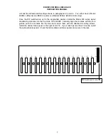
Page 9: ...e Model 400 series signal conditioning modules into the front side of the 4990A Carefully align the modules with the card guides push the modules into the rack and secure them with the attached mounting screws Install the narrow blank panel to the right of slot 16 If your rack has less than 16 cards install the optional blank panels Check that all modules and blank panels are secure in the rack J1...

Page 10: ...ENDEVCO MODEL 4990A RACK INSTRUCTION MANUAL 8 S1 S2 ON S1 S2 ON 4990 1 4990 2 1 2 3 4 5 6 7 8 1 2 3 4 5 6 7 8 1 2 3 4 5 6 7 8 1 2 3 4 5 6 7 8 ...

Page 11: ... snoop mode 5 ON EDAS TX ß à back plane TX X 6 OFF X 7 X X 8 X OFF baud rate 19 2 kbd 4 4 Default Jumper Settings for RS 232 Rack 4990A 2 POS S1 SWITCH SETTING REMARK S2 SWITCH SETTING REMARK 1 ON front panel RX ß à back plane RX OFF use POS1 ON for reversed cable TX RX 2 OFF OFF use POS2 ON for reversed cable RX TX 3 OFF ON straight cable TX ß à TX 4 ON front panel TX ß à back plane TX ON straigh...

Page 12: ...red in such a way as to route the transmit signals from one piece of equipment to the receive signals of another piece of equipment and vice versa The maximum length of cable is 100 meters If you plan on building your own cables see Appendix A OR Connect the RS 232 interface cable between the 9 pin D connector on the 4990A 1 or 4990A 2 and one of the host computer s COM ports The maximum length of...

Page 13: ...reen is the main application screen When the program is run this screen is displayed and the mode is defaulted to OFFLINE as evidenced by the red HARDWARE OFFLINE indicator visible below the ENDEVCO text This spreadsheet like table allows a user to quickly setup channels for an entire system of 400 series units ...

Page 14: ...ANUAL 12 Click on the red HARDWARE OFFLINE indicator to establish communication between the computer and hardware The indicator should turn white and read HARDWARE ONLINE This screen will immediately appear Make your selection and click OK ...

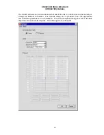
Page 15: ...00 units in a 4990A rack either serially or through an Ethernet connection The Options dialog box is provided to set the appropriate communication parameters for an installation To access the Options dialog box click on the Edit drop down menu and select Options The following screen will appear ...

Page 16: ...ch rack number in the table Below are the steps to assign and store Ethernet addresses for a rack 1 Select a rack row in the table 2 Enter in the table the desired Ethernet addresses for the selected rack 3 Click on the Write Rack button and follow the displayed instructions for setting up the selected rack to receive and store Ethernet addresses 4 Click on the Test Rack button and follow the disp...

Page 17: ...in the IP Address corresponding to the 255s in the Subnet Mask Each device on a network must have a different Host ID portion of the IP address The numbers in the IP Address corresponding to the 0s in the Subnet Mask All devices on a given network must have the same valid Gateway Address if they are communicating across networks Configuring the Model 4990A Rack After entering the IP address subnet...

Page 18: ...roblem and click OK If you suspect the Ethernet NIC cable or hub may be the cause of the failure Identify a vacant serial COM port on the host computer Connect a serial RS 232 cable between this port and the 9 pin D connector on the 4990A Set the DIP switches for serial communication per paragraph 3 3 If the 4990A responds check the hardware NIC cable hub and check for a correct IP address subnet ...

Page 19: ...EMARK 1 OFF ON for snoop mode OFF 2 ON EDAS RX ß à back plane RX OFF 3 OFF OFF ON for snoop mode 4 OFF ON for snoop mode OFF ON for snoop mode 5 ON EDAS TX ß à back plane TX X 6 OFF X 7 X X 8 X OFF baud rate 19 2 kbd On the Options screen click on Test Rack The following window will appear Follow the instructions and click OK The following window will be displayed while the computer is establishin...

Page 20: ...net NIC cable or hub may be the cause of the failure Identify a vacant serial COM port on the host computer Connect a serial RS 232 cable between this port and the 9 pin D connector on the 4990A Set the DIP switches for serial communication per paragraph 4 3 If the 4990A responds check the hardware NIC cable hub and check for a correct IP address subnet mask and gateway address ...

Page 21: ...log output signals are available at the three BNC output connectors and also at one of the four 25 pin D connectors on the 4990A rack Which connector depends on which slot the 433 board resides in See paragraph 6 2 1 for pin assignments 6 1 3 Model 436 Three Channel DC Amplifier The Model 436 should warm up for one hour prior to taking data All three input connectors are 9 pin D The input pin assi...

Page 22: ... Non Smart Sensors connected to a maximum of four OASIS Model 482 Smart ISOTRON Signal Conditioning Cards This Input Breakout Panel provides a quick interface panel to attach BNC input connectors with minimal effort The output of this panel mates to the female double density 26 pin subminiature input connectors of the Model 482 card Pin assignments are as follows Pin Function 2 Signal 1 3 Return 1...

Page 23: ...reakout panel provides an interface panel to quickly attach BNC connectors for DMM s Oscilloscopes and follow on instrumentation The input of this panel mates to the output of the female 9 pin D connectors of the Model 482 Smart ISOTRON amplifier card J3 Pin Function J4 Pin Function 1 Signal channel 4 1 Signal channel 8 2 Return channel 4 2 Return channel 8 3 Shield channel 4 3 Shield channel 8 4 ...

Page 24: ...rack card panel connector 2 channel slot ch signal pin return pin channel slot ch signal pin return pin 1 1 1 16 3 13 5 1 16 3 2 1 2 15 2 14 5 2 15 2 3 1 3 14 1 15 5 3 14 1 4 2 1 17 4 16 6 1 17 4 5 2 2 18 5 17 6 2 18 5 6 2 3 19 6 18 6 3 19 6 7 3 1 22 10 19 7 1 22 10 8 3 2 21 9 20 7 2 21 9 9 3 3 20 8 21 7 3 20 8 10 4 1 23 11 22 8 1 23 11 11 4 2 24 12 23 8 2 24 12 12 4 3 25 13 24 8 3 25 13 system ra...

Page 25: ...e Atmosphere Do not operate the instrument in the presence of flammable gases or fumes Operation of any electrical instrument in such an environment constitutes a safety hazard 7 3 Keep away from live circuits Operating personnel must not remove instrument covers Component replacement and internal adjustments must be made by qualified maintenance personnel Do not replace components with the power ...

Page 26: ...erminal which must be connected to ground before operating the equipment DANGER The DANGER sign denotes a hazard It calls attention to an operating procedure practice condition or the like which could result in injury or death to personnel even during normal operation The WARNING sign denotes a hazard It calls attention to an operating procedure practice condition or the like which if not correctl...

Page 27: ... Check DC voltages inside on back plane Jumpers W2 W4 W7 W8 W9 are labeled with their appropriate voltages Serial cable Ethernet cable connected Type of Ethernet cable to RJ 45 connector on front panel Must be crossover when connecting computer directly to the 4990A straight when connecting the 4990A to hub or repeater Type of serial cable straight TX 2 RX 3 at 4990A end if null modem cable is use...

Page 28: ...output is used check if proper channel is selected in OASIS 2000 menu Model 482 Is the output cable connected to the proper 25 pin D output connector If card has just been powered on exposed to extreme signal or gain has just been switched or cable sensor has just been connected wait 2 minutes for signal to settle down ISOTRON sensors ...

Page 29: ...ress ENDEVCO 30700 Rancho Viejo Road San Juan Capistrano CA 92675 TEL 949 493 8181 FAX 949 661 7231 Email applications endevco com Web Site http www endevco com To return an instrument please Ensure proper packaging preferably the original shipping cartons Prepay shipping and insurance charges Attach the Return Material Authorization RMA number from ENDEVCO and include any information that may be ...

Page 30: ...ENDEVCO MODEL 4990A RACK INSTRUCTION MANUAL 28 cannot be repaired for 300 00 or less ENDEVCO will submit a written quotation for the cost of the repair and or replacement of the unit ...

Page 31: ...oard 482 8 Channel Smart MODAL ISOTRON Board 9 2 Model 400 Series Accessories For a complete list of accessories and options refer to the following documents IMSW2000 Instruction Manual for the OASIS configuration software IM428 Instruction Manual for the two channel PE ISOTRON amplifier IM433 Instruction Manual for the three channel PE ISOTRON amplifier IM436 Instruction Manual for the three chan...

Page 32: ...al crosstalk and can cause phantom collisions This occurs because collisions are detected in twisted pair Ethernet by the simultaneous occurrence of signals on the transmit and receive wire pairs Excessive crosstalk signals can look like simultaneous traffic and can falsely trigger the collision detect circuit This can result in late collisions which are collisions that occur too late in the trans...

Reviews: