ENDEVCO MODEL 4990A RACK
INSTRUCTION MANUAL
7
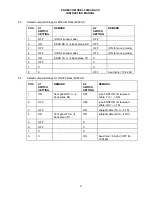
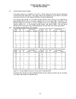
unit and the default switch settings shown in paragraphs 4.3 and 4.4. You either have a Model
4990A-1 (Ethernet and RS232 control) or a Model 4990A-2 (RS232 control only).
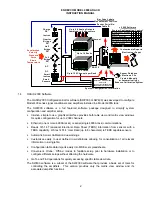
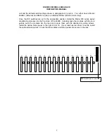
Once the DIP switches are set to the appropriate position, install the Model 400 series signal
conditioning modules into the front side of the 4990A. Carefully align the modules with the card
guides, push the modules into the rack and secure them with the attached mounting screws.
Install the narrow blank panel to the right of slot 16. If your rack has less than 16 cards, install
the optional blank panels. Check that all modules and blank panels are secure in the rack.
J1
J2
J3
J4
J5
J6
J7
J8
J9
J10
J11
J12
J13
J14
J15
J16
S1
S2
DIP Switches S1 and S2

