ENDEVCO 6634C
INSTRUCTION MANUAL
IM6634C
Page 2-5
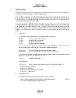
Continue the Calibration procedure listed above for each 6634C channel installed in the rack (/SYS-CAL can be
daisy chained to calibrate all 6634C units at the same time). If all channels Calibrate without errors, the system is
fully calibrated and ready to operate. The operation command instructions are described in Section 3.
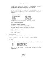
If the optional programmable Filter (Model 35840A) is installed by user in the field, the unit must be recalibrated
for optimum filter performance. Simply repeat the System Calibration described above.
A detailed discussion of the Calibration process is provided in Section 3.7/4.6.
For more detailed testing of the unit, such as frequency response, etc., an external electrical input can be used or
the transducers can be placed on a transducer calibration system (shaker, etc.) for providing a calibrated input at
any frequency of interest.
C.
EXTERNAL ALARM HOOKUPS
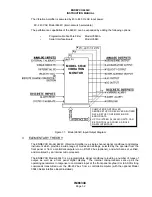
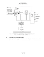
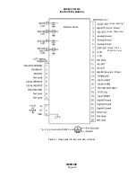
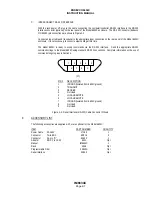
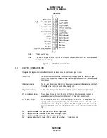
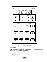
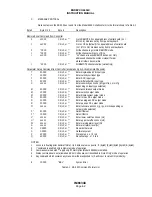
Hookup requirements for alarms are as follows: (Reference Figure 2-1)
NOTE: The maximum sink current available from the 6634C is approximately 20mA, due to a 200 ohm series
resistor.
Pin 4
Analog ground
Pin 14 /Overload
Pin 15 Alarm Alert
Pin 16 Alarm Warning
Pin 17 +5 Volts DC
Pin 19 Alarm Reset
Pin 20 Digital Ground
Setup: Pins 14, 15, and 16 are TTL outputs, normally high.
Alarm Reset: Pin 19 a TTL signal, normally high, may be momentarily shorted to ground to reset the 6634C.

