background image

ENDEVCO 6634C 

INSTRUCTION MANUAL


IM6634C 

Page 4-8 

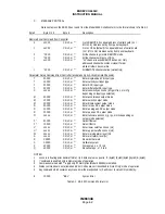
C. 

EXTERNAL FILTER 


To use the 6634C in the external filter mode, install filter between pin 2, “BB-OUT”, and pin 13, “BB-IN”, of the 25 

pin Output connector.  Move jumper W3 (internal to unit) from the 1-2 position to the 3-4 position.  With W3 in the 

3-4 position, either an external filter must be installed, or a jumper must be installed between pins 2 and 13 of the 

Output connector to complete the signal path.  When using an external filter you are still able to use an internal 

filter with the “FILTER IN/OUT” key on the front panel. 


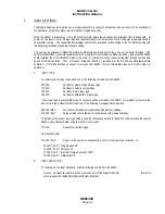
5. 

ALARM 


Warning and Alert alarms are remotely programmed and provide RS-232 signals when the vibration signal exceeds 

preset levels. 


At power-up, the alarm levels are set to the default settings which were previously stored in non-volatile memory. 

A . 

ALARM LEVELS  


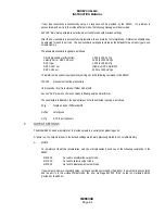
To remotely set the warning and alert Alarm Levels, send the following commands to the 6634C: 


Wnnnnn;   

Set Warning Alarm Level, where nnnnn is % of Full Scale in   


floating point decimal format. Its value is equal to 0.(byte0)(byte1)  


(byte2)(byte3) E (byte4). 


  Annnnn;   

Set Alert Alarm Level, to nnnnn, where nnnnn is % of Full Scale  


in floating point decimal format. Its value is equal to 0.(byte0)  


(byte1)(byte2)(byte3) E (byte4). 


If new Alarm Levels are successfully setup, no response will be provided by the 6634C.  If a problem is 

encountered, and the unit is in Listener/Talker mode, the error message E1XXXX "BEL", setup is not allowed, will 

be provided by the 6634C.   


The Alarm Level is stated in percent of Full Scale, and the allowable levels are from 1.0% to 100.0% of Full Scale.  

Setting an Alarm Level of 100.0% disables the alarm. 


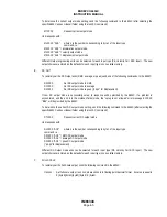
To determine the current Alarm Level settings, send the following commands to the 6634C (after selecting the 

specific 6634C unit as Listener/Talker using the InnXXX; command): 


  W?XXXX ; 


Request current Warning Alarm Level 


  A?XXXX ; 


Request current Alert Alarm Level 


Unit responds with: 


  Wnnnnn "ACK" 


where nnnnn is Warning Alarm Level in floating point decimal format.  


  Annnnn "ACK" 


where nnnnn is Alert Alarm Level in floating point decimal format.  


After the new Alarm Levels are successfully implemented, the unit returns to Normal Mode.  (If Alarm Levels 

cannot be implemented, unit provides "Err" message if in Listener/Talker mode and then returns to normal mode.)  

Different Alarm Levels can be selected for each input type/output units combination.  The new Alarm Level settings 

are stored as the defaults for each input type/output units combination in non-volatile memory.   

Summary of Contents for 6634C

Page 1: ...IM6634C Revision G April 9 2007 MODEL 6634C VIBRATION AMPLIFIER INSTRUCTION MANUAL San Juan Capistrano California U S A ...

Page 2: ... CHECKING OUT UNIT 2 2 7 CONNECTIONS 2 4 8 ACCESSORY LIST 2 7 9 JUMPER CONFIGURATION 2 8 SECTION 3 OPERATING INSTRUCTIONS 1 KEYBOARD AND DISPLAY 3 1 2 NORMAL MODE 3 1 3 INPUT SETTINGS 3 2 4 OUTPUT AND DISPLAY SETTINGS 3 4 5 PROGRAMMABLE FILTER 3 5 6 ALARM 3 6 7 STORE RECALL SETTINGS KEYBOARD LOCKUP AND BUS ADDRESS 3 6 8 EXTERNAL CALIBRATION 3 7 SECTION 4 OPERATION WITH RS 232 INTERFACE 1 OVERVIEW ...

Page 3: ...HASE RESPONSE FOR 6634C A 6 6 INTERFACE TO 6726 TRACKING FILTER A 7 7 INTERFACE WITH 6634A INSTALLATIONS A 8 LIST OF ILLUSTRATIONS 1 1 MODEL 6634C INPUT OUTPUT DIAGRAM 1 2 1 2 SIMPLIFIED BLOCK DIAGRAM OF THE MODEL 6634C 1 4 2 1 WIRING DIAGRAM FOR INPUT AND OUTPUT CONNECTORS 2 6 2 2 SERIAL INTERFACE CABLE CONNECTOR PINOUTS 2 7 2 3 INPUT OUTPUT CONNECTOR PINOUTS 2 8 2 4 JUMPER LOCATIONS ON MAIN BOAR...

Page 4: ...on 2g pk to 200 g pk Full Scale Velocity 1 0 ips pk to 100 ips pk Full Scale Displacement 0 5 mils to 50 mils pk pk Full Scale DC Programmable Output can be set to Acceleration 2g pk to 200 g pk Full Scale Velocity 1 0 ips pk to 100 ips pk Full Scale Displacement 0 5 mils to 50 mils pk pk Full Scale The DC Output can also be programmed to represent true RMS average or peak pk pk for displacement T...

Page 5: ...Diagram 3 ELEMENTARY THEORY The ENDEVCO Model 6634C Vibration Amplifier is a single channel signal conditioner and display instrument which provides a wide range of modes and settings selected by the operator from the front panel or from a controller computer via an RS 232 bus optional and which are set verified and monitored by an internal microprocessor The ENDEVCO Model 6634C is a programmable ...

Page 6: ...grammable from the front panel or over the RS 232 bus with the optional Serial Interface The External Filter can be used with or without the programmable filter installed See Section 4 4 C C INTEGRATORS AND ANALOG OUTPUTS The filtered or unfiltered output can be integrated once to provide velocity data or twice to provide displacement data The filtered or unfiltered signals are delivered to the Ac...

Page 7: ...RS RANGE AMPL IFIER AND A D D A CONVERTERS ACCELERATION VELOCITY DISPLACEMENT BROADBAND AC OUT DC OUT MICROCOMPUTER CONTROLLER SERIAL INTERFACE optional MODEL 35843 RS 232 BUS Figure 1 2 Simplified block diagram of the Model 6634C Settings are implemented by keyboard inputs or through software commands over the RS 232 bus 4 PERFORMANCE DATA AND SPECIFICATIONS A Data Sheet and set of current Specif...

Page 8: ... no power switch and the unit derives its power from the rear power cable connector The line voltage selection switch is inside the unit and should be checked to ensure that it is correctly set WARNING REMOVE POWER CORD FROM UNIT BEFORE OPENING CASE TO PREVENT ELECTRICAL SHOCK 3 INSTALL OPTION BOARDS Optional boards may be installed by the user or at the factory CARE MUST BE TAKEN when unwrapping ...

Page 9: ...r a few seconds if the optional serial interface is installed The front panel digital display will display an Error Message if a malfunction is detected Front panel error messages which may occur at power up are Err Description Acknowledge by Err2 EPROM Checksum Error System Stop Err3 RAM Error System Stop Err4 Setup RAM Checksum Error ENTER Err5 Calibration RAM Checksum Error ENTER Err6 Keyboard ...

Page 10: ...al Display shows Cutoff 3 dB Frequency LOWER CUTOFF Digital Display shows Cutoff 3 dB Frequency ALARM WARNING Digital Display shows Warning Setting FS ALARM ALERT Digital Display shows Alert Setting FS RESET Pressing RESET resets both alarm settings MULTIPLE KEYPRESS UNIT RESPONDS WITH ENTER 3 Digital Display shows Serial Interface Address ENTER 1 Store Setup to Non volatile Memory ENTER 6 Recall ...

Page 11: ...C units can be daisy chained with a single computer controller All 6634C can receive commands simultaneously from controller but only one at a time can be made Listener Talker see Section 4 Operation with RS 232 Interface 7 CONNECTIONS Operating conditions and input output connections The ENDEVCO Model 6634C Vibration Amplifier may be located in a normal laboratory operating environment Specified ...

Page 12: ...he Calibration process is provided in Section 3 7 4 6 For more detailed testing of the unit such as frequency response etc an external electrical input can be used or the transducers can be placed on a transducer calibration system shaker etc for providing a calibrated input at any frequency of interest C EXTERNAL ALARM HOOKUPS Hookup requirements for alarms are as follows Reference Figure 2 1 NOT...

Page 13: ...NDEVCO 6634C INSTRUCTION MANUAL IM6634C Page 2 6 MODEL 6634C pin is grounded at 6634C end Fixed 50mV g Fixed 100mV ips Fixed 100 or 200mV mil p p Figure 2 1 Wiring diagram for input and output connectors ...

Page 14: ...ia the RS 232 interface Send the appropriate RS 232 command strings to the Model 6634C using standard RS 232 conventions Complete information on the use of command strings is given in Section 4 1 2 3 4 5 6 7 8 9 J7 PIN DESCRIPTION 1 ISOGND Isolated from 6634C ground 2 TRANSMIT 3 RECEIVE 4 Not Used 5 LOCAL REMOTE 6 LOCAL REMOTE 7 ISOGND Isolated from 6634C ground 8 Not Used 9 Not Used Figure 2 2 Se...

Page 15: ...Velocity J4 B is tied to signal ground This configuration is used with 2 wire velocity coil inputs 2777 Acceleration Output This configuration supplies 24VDC to the 2777 on the J4 A input pin and couples the acceleration signal to the signal conditioner input J4 B is tied to signal ground 2777 Velocity Output 24VDC is supplied to the 2777 on the J4 A input pin J4 B is tied to signal ground The inp...

Page 16: ...34C INSTRUCTION MANUAL IM6634C Page 2 9 W8 W8 W1 W1 W9 W9 W9 W9 W8 W8 W1 W1 DRCC VELOCITY DRCC ACCELERATION V VELOCITY DIFFERENTIAL R ISOTRON DEFAULT SET UP MODEL 35840A Figure 2 4 Jumper Locations on Main Board ...

Page 17: ...l and the keyboard area lower panel The display area is divided into three sections DIGITAL READOUT four digit seven segment numeric displays ALARM INDICATORS two individual LEDs Warning and Alert OUTPUT INDICATORS six individual LEDs Three for mode of operation g ips mils Three for DC scaling RMS Avg Pk The keyboard is divided into five sections INPUT OUTPUT FILTER ALARM ENTER 2 NORMAL MODE In th...

Page 18: ...cept inputs from a variety of transducers and can be set to the sensitivity of the transducer so that the outputs are normalized to engineering units When the 6634C is powered up it is in the LOCAL MODE where the unit takes its instructions from the keyboard At power up the input is set to the default input type and input sensitivity which was previously stored in non volatile memory The Digital R...

Page 19: ...S in the Normal Mode will cause the Digital Readout Indicator to flash the present sensitivity setting of the 6634C The indicator will flash the sensitivity setting with the appropriate units for the selected input type as follows pC g Single ended or Differential PE mV ips velocity coil or DRCC VEL OUT mV g RCC input or DRCC ACC OUT While the INPUT SENSITIVITY is being indicated the ALARM and OUT...

Page 20: ...f To change the present setting press DC OUT again The display will scroll to another output choice each time DC OUT is pressed When the desired choice is displayed press ENTER The new output choice is implemented and the unit returns to Normal Mode The unit automatically returns to Normal Mode if no key is pressed for about 20 seconds Different DC Output units can be selected for each input type ...

Page 21: ...s ENTER To change the present setting press IN OUT again The display will toggle between in and Out each time IN OUT is pressed When the desired choice is displayed press ENTER The new filter condition choice is implemented and the unit returns to Normal Mode The unit automatically returns to Normal Mode if no key is pressed for about 20 seconds A different filter condition can be selected for eac...

Page 22: ...de will cause the Digital Readout Indicator to flash the present corresponding Warning or Alert Alarm Level of the 6634C While the Alarm Level is being indicated the ALARM and OUTPUT displays are off To change the present setting type in the desired Alarm Level using the numeric keys The Alarm Level is stated in percent of Full Scale and the allowable levels are from 1 0 to 100 0 of Full Scale Set...

Page 23: ...the front panel displays ERRØ Input the new desired address from 1 to 16 and press ENTER Unit returns to normal mode with new address installed Address Ø disables REMOTE operation 8 EXTERNAL CALIBRATION In External Calibration critical parameters of the 6634C are adjusted to ensure performance within specification Before initiating the External Calibration of the 6634C an external calibration sour...

Page 24: ...ake lines implemented The internal RS 232 buffer is 600 bytes long and commands longer than the buffer size may be lost The RS 232 interface is a 9 pin D connector and the internal transmitter receiver complies with EIA RS 232C Standard Section Two Electrical Signal Characteristics except that the input impedance of the receiver is higher and transmitter can be tristate to allow multidrop scheme M...

Page 25: ...ding on input type selected M 0XXXX CR LF or Enter acceleration output mode M 1XXXX CR LF or Enter velocity output mode M 2XXXX CR LF or Enter displacement output mode D 0XXXX CR LF or Enter rms as DC output mode D 1XXXX CR LF or Enter average as DC output mode D 2XXXX CR LF or Enter peak as DC output mode O nnnnn CR LF or Enter full scale as nnnnn g ips or mils depending on output mode selected F...

Page 26: ...ed from 6634C the unit immediately reverts to LOCAL mode of operation A INPUT TYPE To remotely set the Input Type send one of the following commands to the 6634C T0XXXX Set input to single ended PE input type T1XXXX Set input to velocity coil input type T2XXXX Set input to RCC input type T3XXXX Set input to differential PE input type If new input type is successfully setup no response will be prov...

Page 27: ...nd the following command to the 6634C S XXXX Request current input sensitivity Unit responds if unit is in Listener Talker mode with Snnnnn ACK where nnnnn is sensitivity in floating point decimal format The sensitivity is indicated in the appropriate units for the selected input type as follows pC g Single ended or Differential PE mV ips velocity coil mV g RCC input optional 3 OUTPUT SETTINGS The...

Page 28: ...t If new DC output mode is successfully setup n o response will be provided by the 6634C If a problem is encountered and the unit is in the Listener Talker mode the setup is not allowed error message E1XXXX BEL will be provided by the 6634C To determine the current DC output mode setting send the following command to the 6634C after selecting the specific 6634C unit as Listener Talker using the In...

Page 29: ...ings are stored as the defaults for each input type and output mode combination in non volatile memory 4 PROGRAMMABLE FILTER The optional programmable filter may be remotely set to limit the frequency range of the signal being measured and output At power up the filter corner frequencies are set to the default settings which were previously stored in non volatile memory A FILTER IN OUT To remotely...

Page 30: ...f 3dB Frequency ranges as follows Lower Cutoff High Pass 5 to 500 Hz Upper Cutoff Low Pass 50 to 5000 Hz Jumper selected 100 to 10 000 Hz Jumper selected NOTE The 5 frequency point can be obtained by multiplying the Cutoff Frequency by 1 2 for the high pass filter and by 0 833 for the low pass filter To determine the current filter cutoff settings send the following commands to the 6634C after sel...

Page 31: ...e in floating point decimal format Its value is equal to 0 byte0 byte1 byte2 byte3 E byte4 If new Alarm Levels are successfully setup no response will be provided by the 6634C If a problem is encountered and the unit is in Listener Talker mode the error message E1XXXX BEL setup is not allowed will be provided by the 6634C The Alarm Level is stated in percent of Full Scale and the allowable levels ...

Page 32: ...ion signal subsequently drops below the corresponding Alarm Level the Alarms must be Reset to provide valid current indications To remotely Reset the Alarms send the following command to the 6634C RXXXXX Reset both alarms 6 EXTERNAL CALIBRATION In External Calibration critical parameters of the 6634C are adjusted to ensure performance within specification Before remotely initiating the External Ca...

Page 33: ... setup and implement that setup in the 6634C send the following command over the RS 232 bus QnXXXX Recall setup n where n 0 to 9 If an attempt is made to recall a setup which was not previously stored the following response is sent from the 6634C if unit is set to Listener Talker mode E1XXXX BEL Setup not previously stored 8 STATUS Status is sent to the controller in response to specified status r...

Page 34: ...ksum Error unit has proceeded with no calibration D DATA REQUEST The 6634C can be requested to output the current vibration level data over the RS 232 bus The vibration data can be requested by sending the following query after selecting the specific 6634C unit as Listener Talker using the InnXXX command V XXXX Request current vibration data Unit may respond with either of the following messages E...

Page 35: ...010 022 18 12 00111101 075 61 3D h 01101000 150 104 68 DC3 00010011 023 19 13 00111110 076 62 3E i 01101001 151 105 69 DC4 00010100 024 20 14 00111111 077 63 3F j 01101010 152 106 6A NAK 00010101 025 21 15 01000000 100 64 40 k 01101011 153 107 6B SYN 00010110 026 22 16 A 01000001 101 65 41 l 01101100 154 108 6C ETB 00010111 027 23 17 B 01000010 102 66 42 m 01101101 155 109 6D CAN 00011000 030 24 1...

Page 36: ...nic components and void the warranty of the system B IN CASE OF ACCIDENTS If any accidental damage to the equipment occurs such as dropping the rack spilling liquids on the case etc take the following steps During Operation Power down suspends the test and visually examines the equipment If no damage is noticed power up and repeat calibration as described in Section 2 If damage is observed or cali...

Page 37: ...zing repair calibration along with a full explanation of the failure or symptoms observed to help in fixing the problem A copy of a Report of Failure Checklist is attached immediately following this section to assist in describing the failure that occurred The instrument will be repaired calibrated returned and invoiced for the actual repair charges If the instrument cannot be repaired for 300 or ...

Page 38: ...O 6634C INSTRUCTION MANUAL IM6634C Page 5 3 A POWER UP After replacing the EPROM follow the Power Up procedure in Section 2 U38 POWER SUPPLY MODULE COMPONENT SIDE FUSE Figure 5 1 EPROM Location on Main Board ...

Page 39: ...plifier operates at a fixed gain of 0 0606 mV mV B SENSITIVITY AMPLIFIER The Sensitivity Amplifier input is programmable switched between the Charge Amplifier output and the Instrumentation Amplifier output The Sensitivity Amplifier gain can be programmable adjusted from 1 1 to 110 in steps of 0 1 The output of the sensitivity amplifier is available at the BB OUT connector pin It is also routed to...

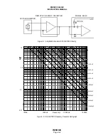
Page 40: ...NSOR OUTPUT SWING Each 6634C input channel contains a constant current supply see Figure A 2 for an RCC or ISOTRON transducer This supply is set up to deliver 8 6mA 10 to the RCC or ISOTRON from a voltage source of 22 2 Volts the compliance voltage The AC data signal from the remote device travels along the same wire carrying DC power to the device A typical ISOTRON operates at a bias voltage of 1...

Page 41: ...ENDEVCO 6634C INSTRUCTION MANUAL IM6634C Page A 3 A Figure A 1 Simplified block diagram of the amplification scheme of the Model 6634C NOTE See Figure 2 1 for connector and pin designations ...

Page 42: ... RGE C ONVERTER MODEL 6634C Figure A 2 Simplified Schematic of RCC ISOTRON Circuitry 100 000 10 000 Hz 1000Hz 100Hz 0 01 0 1 1 0 10 V mA Frequency 1000 pF 2000 pF 3000 pF 5000 pF 10 000pF 20 000pF 30 000pF 50 000pF 100 000pF Figure A 3 RCC ISOTRON Frequency Response Nomograph ...

Page 43: ...filter between pin 2 BB OUT and pin 13 BB IN of the 25 pin Output connector Move jumper W3 internal to unit from the 1 2 position to the 3 4 position With W3 in the 3 4 position either an external filter must be installed or a jumper must be installed between pins 2 and 13 of the Output connector to complete the signal path When using an external filter you are still able to use an internal filter...

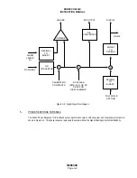
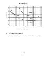
Page 44: ...BRATION CONSTANTS DC SCALER RMS AVG OR PK PK PK FOR DISPLACEMENT DECIMAL TO BINARY FULL SCALE SETTING Figure A 4 Digital Signal Flow Diagram 5 PHASE RESPONSE FOR 6634C The 6634C Phase Response for Broadband output Acceleration output Velocity output and Displacement output are shown in Figure A 5 This phase response represents the output without the Signal Filtering option Model 35840A ...

Page 45: ...RUCTION MANUAL IM6634C Page A 7 Figure A 5 Phase Response for 6634C 6 INTERFACE WITH 6634A INSTALLATIONS The 6634C may be interfaced with old 6634A installations using an Endevco interface cable Endevco Part Number 29685 ...

Reviews: