INSTRUCTION MANUAL
For Model 7255A
,
Pyrotron™ Accelerometer
IM7255A, Revision A
IMPORTANT: Constant current source of 8 mA to 20 mA is recommended if the
total cable length is to exceed 50 ft.
The Endevco Model 7255A is a piezoelectric accelerometer with integral electronics and built-in
mechanical filter designed specifically for near-field (close-range) pyrotechnic shock measurement. Due to
severe environment in which the accelerometer is installed, certain special precautions must be observed
when mounting the accelerometer to avoid measurement errors.
Surface Preparation
The surface on which the accelerometer rests should have a surface roughness of 32 micro inches rms or
better. Drill and tap a 0.25-28 UNF-2B thread, 0.25 inches (6.35 mm) deep minimum, with less than ±1°
perpendicularity.
Adhesive mounting is not recommended due to the possibility of inducing zeroshift and other errors.
Installation Procedure
1. Cut two small pieces of insulation tubings (shrink tubing recommended), approximately 3/8"
(9.52 mm), and insert them onto the wires of the Model 3024 Cable prior to soldering.
2. Under good lighting condition and with small soldering tool, solder the Red wire to the positive
terminal and the Black wire to the ground terminal. Slip the insulation tubing over the solder
joints.
3. Mount the accelerometer to the test article at 30 lbf-in (3.5 Nm) by using a torque wrench. Be
careful not to damage the cable assembly or the solder joints during installation. Unwind and
straighten the cable if necessary after the accelerometer has been mounted.
For best result, clean threads and apply thread-locking compound, such as Loctite™, before
mounting.
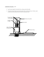
4. Form a small loop with the cable (for strain relief) above the solder joints and slip the supplied
protective vinyl boot over the transducer as indicated. In very high-g applications, it may be
necessary to glue the vinyl boot to the accelerometer body to prevent it from coming off.
Do not let the protective vinyl boot touch the top of the cable loops. Restricting the vertical
movements of the cable loop may cause linearity error in the mechanical filter.
IM7255A, Page 2


