background image

Fastlane

®

 Pro Swim Unit Installation

Fastlane

®

 Pro Swim Unit Installation


Section 7 

INSTALLATION OF YOUR WALL MOUNT FASTLANE PRO


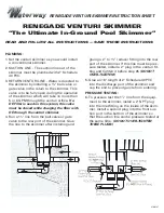
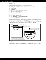
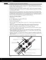
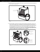
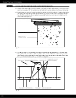
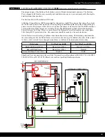
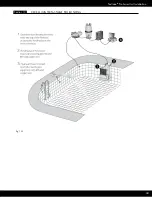
Fill the pool up to operating level, which should be approximately 1-1/2" (38mm) below the mounting rods.


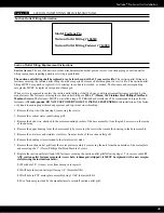
 Apply Teflon sealant to the threads of each 1-1/2" (38mm) MPT x 1" (25mm) FPT bushing reducer and 

thread them into the thru-wall fittings. Then apply Teflon thread sealant to the threads of the liquid tight 

fittings and thread them into the bushing reducers (Fig 7.1).


Fig. 7.1


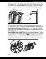
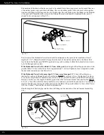
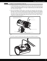
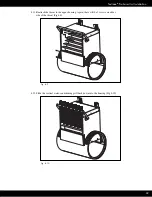
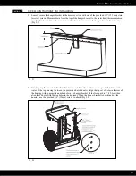
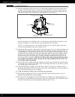
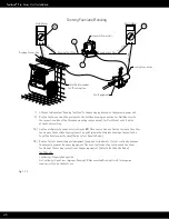
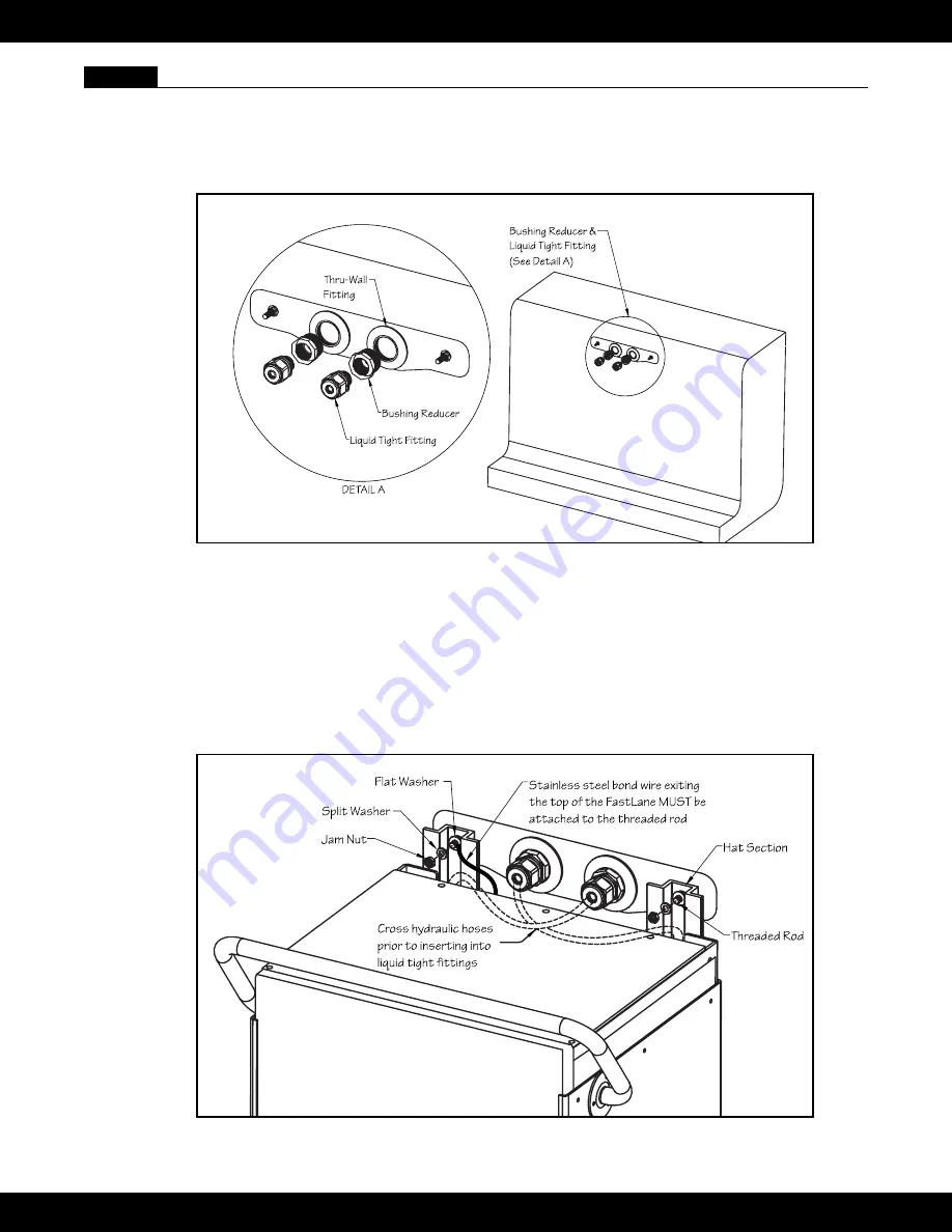
   Using two people, carefully lower the Fastlane Pro into the pool. Align the holes at the top of the protective 

hat sections with the threaded mounting rods and rest the Fastlane Pro into place. The Fastlane Pro will 

hang from the mounting rods. Place a 3/8” (9,5mm) flat washer onto each mounting rod making sure it’s 

flush against the hat channel. Secure the stainless steel bond wire that exits the top of the Fastlane Pro 

to the threaded rod. Place a 3/8” (9,5mm) lock washer and jam nut onto each threaded rod to secure the 

Fastlane Pro (Fig 7.2).


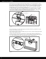
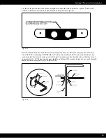
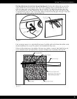
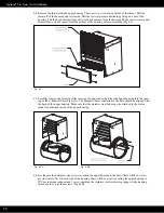
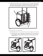
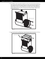
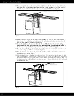
 Insert the hoses into the conduits. The hoses should cross over themselves prior to inserting into the conduit 

(i.e. left hose will be inserted into the right conduit) 


Fig. 7.2


34

Summary of Contents for FASTLANE PRO

Page 1: ...FASTLANE PRO By Endless Pools OWNER S MANUAL...

Page 2: ...the local building and health code for more information WARNING Before each use examine the unit for damage or signs of wear Do not use the product if found in this condition Contact Endless Pools Cu...

Page 3: ...tion before or during spa use may lead to unconsciousness with the possibility of drowning La consommation d alcool de drogues ou de m dicaments avant ou pendant l utilisation du spa peut entra ner un...

Page 4: ...water pipe or conduit within 5 feet 1 5 m of the unit Un connecteur de fil est fourni sur cette unit pour connecter un conducteur en cuivre solide d au moins 8 4 mm2 8 AWG entre cette unit et tout qu...

Page 5: ...AX ATION WARNING WATER TEMPERATURE IN EXCESS OF 100 F 38 C CAN BE INJURIOUS TO YOUR HEALTH AVERTISSEMENT IL PEUT TRE DANGEREUX POUR LA SANT DE SE PLONGER DANS DE L EAU PLUS DE 38 C 100 F WARNING BEFOR...

Page 6: ...d before bathers are allowed to use the unit Suction Outlet Fitting User Maintenance Instructions Field Modifications Any field modification made to the suction outlet fitting not authorized by Endles...

Page 7: ...ving Your Fastlane Pro 8 Wall Mount Bracket 9 Gunite Pool 9 Steel Polymer Pool with a Vinyl Liner 13 Gunite Pool with a Vinyl Liner 18 Fiberglass Pool 23 Junction Box And 1 2 Run Hoses 27 Assembly Of...

Page 8: ...ates a 16 40 6cm diameter propeller The Power Unit is activated using a 3 button radio frequency remote control that can turn the unit on and off and adjust the speed It is best if the Power Unit is w...

Page 9: ...the other pool equipment and if possible long hydraulic runs should be avoided because of pressure loss If you wish to have a run greater than 25 7 6m you must transition from 3 8 9 5mm hydraulic hos...

Page 10: ...1 2 38mm Thru Wall Fitting 2 1 1 2 38mm MPT x 1 25mm FPT Bushing Reducer 2 1 25mm Liquid Tight Fitting 1 25mm Liquid Tight Fitting 1 1 2 38mm x 1 25mm Bushing Reducer Thru Wall Fitting Rubber Gasket T...

Page 11: ...face of the pool wall as shown in Figures 4 2 and 4 5 The area below the bracket should be no more than 5 degrees less than the vertical down to at least 39 99cm below the waterline The Fastlane Pro i...

Page 12: ...ower Unit If the Hydraulic Power Unit is more than 25 7 6m away from pool 25 7 6m of flexible pipe a junction box and an additional length of flexible pipe MUST be employed It is at the junction box w...

Page 13: ...g grid In most cases this will be a connection at the rebar Verify ALL bonding connections are tight before shooting gunite Fig 4 4 Fig 4 4 Prior to shooting gunite it is critical that the opening of...

Page 14: ...sher 2 3 8 9 5mm Stainless Steel Hex Head Bolt Sacrificial Bolt 2 1 1 2 38mm Star Thru Wall Fitting 2 1 1 2 38mm MPT x FSlip Adapter 2 1 1 2 38mm MPT x 1 25mm FPT Bushing Reducer 2 1 25mm Liquid Tight...

Page 15: ...ling onto the threaded rod so that half of the hex coupling is threaded onto the rod and the other half that s facing the pool is protruding off the threaded rod Tighten the jam nut so that its flush...

Page 16: ...ose is required to make the hydraulic connections at the Power Unit If the Hydraulic Power Unit is more than 25 7 6m away from pool 25 7 6m of flexible pipe a junction box and an additional length of...

Page 17: ...bonding grid In most cases this connection will be at the pools existing equipment heater pump etc that s presumably already tied into the bonding grid of the pool Verify these connections are tight b...

Page 18: ...ole using a sharp utility knife Cut the holes as small as possible for the threaded rods Fig 4 13 Fig 4 13 Using a scratch awl poke the holes out in each star thru wall fitting holes located in 12 3 6...

Page 19: ...hreaded Stud 4 3 8 9 5mm Stainless Steel Jam Nut 2 3 8 9 5mm Stainless Steel Flat Washer 2 3 8 9 5mm Stainless Steel Lock Washer 2 3 8 9 5mm Rubber Washer 2 3 8 9 5mm Stainless Steel with Neoprene Sac...

Page 20: ...ed rod Tighten the jam nut so that its flush with the hex coupling to prevent the hex coupling from threading further onto the rod Fig 4 16 Fig 4 16 On the backside of the bracket position each thread...

Page 21: ...t If the Hydraulic Power Unit is within 25 7 6m of the pool Each length of flexible pipe should exit the ground within 4 1 2m of the Power Unit Approximately 4 1 2m of hydraulic hose is required to ma...

Page 22: ...will be a connection at the rebar Verify ALL bonding connections are tight before shooting gunite Fig 4 20 Bonding Clamp See Detail A Bonding Clamp Threaded Rod DETAIL A 8 Solid Copper Wire MUST BE AT...

Page 23: ...ed rods Fig 4 22 Fig 4 22 Using a scratch awl poke the holes out in each star thru wall fitting holes located in 12 3 6 9 clock positions and install the thru wall faceplates using the screws provided...

Page 24: ...ht Fitting Remove the hardware from the PVC bracket In this application the bracket will serve primarily as a tem plate Position the bracket on the pool wall where the Fastlane Pro will be placed Alig...

Page 25: ...into each PVC washer making sure there is a flat washer and jam nut on the back side of the PVC washer Fig 4 26 DETAIL A Position and install each PVC washer and threaded rod as sembly against the bac...

Page 26: ...ydraulic Power Unit is within 25 7 6m of the pool Each length of flexible pipe should exit the ground within 4 1 2m of the Power Unit Approximately 4 1 2m of hydraulic hose is required to make the hyd...

Page 27: ...quipment heater pump etc that s presumably already tied into the bonding grid of the pool Verify these connections are tight before pouring concrete Fig 4 29 Bonding Clamp 8 Solid Copper Wire DETAIL A...

Page 28: ...r future maintenance Junction Box Kit optional includes 1 Junction Box 4 1 1 2 38mm FSlip x 1 1 2 38mm MPT Adapters 4 1 1 2 38mm Conduit Locknuts 1 Roll of Anti Corrosion Tape The 1 1 2 38mm PVC flex...

Page 29: ...ling or working with any of the stainless steel components of the swim unit The ends can be sharp The first step is to remove the two circular end caps from each side of the cylindrical base There are...

Page 30: ...sing the upper housing Place the upper housing into the open ing of the cylindrical base Fig 6 4A The hydraulic hoses connected to the base should be aligned with the back of the upper housing Make su...

Page 31: ...he back of the upper housing There will be 8 screws per hat section Fig 6 5 Fig 6 5 6 8 Pull any excess hose out of the hat channel 6 8a If the hydraulic hoses are to be run up and over the pool deck...

Page 32: ...izontal grill Then feed the wire up between two of the turning vanes Place the stainless steel wire from the motor mount in the base around the bottom screw on the left side before tightening down on...

Page 33: ...tallation 6 11 Reattach the throat to the upper housing Again there will be 2 screws on either side of the throat Fig 6 9 Fig 6 9 6 12 Slide the vertical water conditioning grill back down into the ho...

Page 34: ...aligned with holes in the end caps Position the arced cover strips over the end caps making sure to align the hole in the arced cover strips with the holes in the stainless end caps and the internal P...

Page 35: ...lower the Fastlane Pro into the pool Align the holes at the top of the protective hat sections with the threaded mounting rods and rest the Fastlane Pro into place The Fastlane Pro will hang from the...

Page 36: ...e coping The coping MUST fully support the hose cover tray The tray will be centered to the Fast lane Pro If the pool has bullnose coping it is acceptable for the hose cover tray to be slightly out of...

Page 37: ...taken remove the hanger bracket from the tray Fig 9 1 Fig 9 1 9 2 Carefully lay the assembled Fastlane Pro down on its front face There are six pre drilled holes in the center of the top housing betwe...

Page 38: ...he hose cover tray Attach a 8 AWG bare copper wire to the bonding lug attached to the hose cover tray and then incorporate that wire into the pool s bonding grid 9 6 Place the Fastlane Pro lid onto th...

Page 39: ...ve the Power Unit is accessible Access to the Power Unit Controller is essential Fig 10 1 10 2 Carefully remove the Power Unit from the packaging Note The Power Unit is very heavy To remove the Power...

Page 40: ...the chance of electrical shock The Hy draulic Power Unit requires one single phase 220v 30amp GFCI protected service All connections should be made by a licensed electrician Line 1 Line 2 Neutral Gro...

Page 41: ...tions should be made by a licensed electrician United States wire color coding is different than international color coding The following chart identifies the color coding used in the United States as...

Page 42: ...na provided by threading it onto the coaxial connection on the left side of the Power Unit Controller s enclosure Turn on the unit by pressing and holding the ON OFF button button in the center of the...

Page 43: ...ded rod of the wall mount bracket The threaded rods of the bracket must be tied into the pool s bonding grid Before shooting gunite 8 solid copper must be attached to each bonding clamp These wires wi...

Page 44: ...Fastlane Pro Swim Unit Installation Section 13 WALL MOUNTED FASTLANE PRO BONDING Fig 13 1 43...

Page 45: ...Fastlane Pro Swim Unit Installation Section 13 DECK MOUNTED FASTLANE PRO BONDING Fig 13 2 44...

Page 46: ...Mount units it will be at the hose cover tray 3A Set the multimeter to resistance continuity Place one test lead on the test wire and the other test lead on the Fastlane bonding connection point where...

Page 47: ...information below MONTH YEAR INSTALLED________ 2 Hand the installation manual containing the above information to the customer to be stored with other important pool related documentation Section 16...

Page 48: ...and 7 8 total alkalinity between 80 and 120 ppm salt chlorine levels below 4000 ppm and total dissolved solids below 7000 ppm Failure to properly bond the Fastlane Pro or maintain proper water chemist...

Page 49: ...fasteners is 25 inch pounds DO NOT USE POWER TOOLS TO INSTALL FASTENERS Start installation of the fasten er by hand to ensure proper thread engagement and to prevent cross threading 1 Remove the top...

Page 50: ...Endless Pools 1601 Dutton Mill Rd Aston PA 19014 2931 800 910 2714 US 610 497 8693 fax www myendlesspool com D30001 0820 Copyright 2020 Wellness Marketing Corporation...

Reviews: