background image

Contact 1-800-762-1142 for assistance.

Do not return to place of purchase.

®

Owner’s manual: model 200209 outdoor patio heater          7/28/04

15

Contact 1-800-762-1142 for assistance.

Do not return to place of purchase.

®

Owner’s manual: model 200209 outdoor patio heater          7/28/04

16

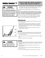
WARNING

FOR YOUR SAFETY

Be careful when attempting 
to manually ignite this heater. 
Holding in the control know for 
more than 10 seconds before 
igniting the gas will cause a 
ball of flame upon ignition.

•  If for some reason your ignitor fails to deliver a spark, your heater can 

be started by inserting a lit match through the pilot view hole while 
pushing the control knob in while in the PILOT position.

If you experience any ignition problem consult “Troubleshooting” on 
page 17.

Caution:  Avoid inhaling fumes emitted from the heater’s first use.  
Smoke and odor from the burning of oils used in manufacturing will 
appear.  Both smoke and odor will dissipate after approximately 30 
minutes.  The heater should NOT produce thick black smoke.

Note:

 The burner may be noisy when initially turned on.  To eliminate 

excessive noise from the burner, turn the Control Knob to the Pilot 
position.  Then, turn the knob to the level of heat desired.

When heater is ON:

Emitter screen will become bright red due to intense heat. The color is 
more visible at night. 

Burner will display tongues of blue and yellow flame.  These flames 
should not be yellow or produce thick black smoke, indicating an 
obstruction of airflow through the burners. The flame should be blue 
with straight yellow tops. 

If excessive yellow flame is detected, turn off heater and consult 
“Troubleshooting” on page 17.

Re-lighting

Note:

  For your safety, Control Knob cannot be turned OFF without first 

depressing Control Knob in PILOT position and then rotating it to OFF.

Turn Control Knob to OFF.

Wait at least 5 minutes, to let gas dissipate, before attempting to relight 
Pilot.

Repeat the “Lighting” steps on prior page.

Shut Down

Turn Control Knob clockwise to Pilot. (Normally, burner will make a slight 
popping sound when extinguished.) Burner will extinguish but Pilot will 
remain ON.

To extinguish Pilot, depress Control Knob and continue to turn it 
clockwise to OFF.

Turn Tank Valve clockwise to OFF and disconnect Regulator when 
heater is not in use.

Note:

  After use, some discoloration of the emitter screen is normal.

WARNING

FOR YOUR SAFETY

Heater will be hot after use. 
Handle with extreme care.

Summary of Contents for 200209

Page 1: ...Outdoor Use Only Outside any enclosure Solamente Para Uso En Exteriores Fuera de cualquier recinto WARNING FOR YOUR SAFETY Improper installation adjustment alteration service or maintenance can cause injury or property damage Read the installation operation and maintenance instructions thoroughly before installing or servicing this equipment ...

Page 2: ...alteration service or maintenance can cause injury or property damage Read the installation operation and maintenance instructions thoroughly before installing or servicing this equipment WARNING California Proposition 65 Chemicals known to the state of California to cause cancer birth defects or other reproductive harm are created by the combustion of propane WARNING FOR YOUR SAFETY Purchaser ass...

Page 3: ...re Gas Line 11 Step 11 Connect Gas Line To Tank 11 Step 12 Check for Leaks 12 Step 13 Replace Engine Access Panel 13 Step 14 Install Igniter Battery Electronic Ignition Models Only 13 Operation Before Turning Gas Supply ON 14 Before Lighting 14 Lighting 14 Re Lighting 15 Shutdown 15 Operation Checklist 16 Troubleshooting 17 Maintenance 18 Storage 19 Service 19 Warranty 20 Specifications 21 The use...

Page 4: ...Do not alter heater in any manner The pressure regulator and hose assembly supplied with the appliance must be used and replacements must be those specified by the manufacturer Inspect heater before each use If a damaged part is detected do not operate until an original equipment replacement part has been properly installed Use of unauthorized parts will void warranty and create an unsafe conditio...

Page 5: ...ders and insects can create a dangerous condition that may damage heater or make it unsafe Keep burner area clean of all spiders webs or insects Inspect heater before each use Have heater inspected annually and repairs should be made by a qualified service person Check heater immediately if any of the following conditions exist The smell of gas in conjunction with extreme yellow tipping of burner ...

Page 6: ...ly 56 01 188 Legs 3 56 01 193 Base 56 01 329 Weight Plate 56 01 198 Hardware Used in Picture Qty Description Step s 1 Carriage Bolt 3 3 8 16 x 3 3 4 Zinc Plated Bolt 56 01 199 12 Bolt 1 2 1 4 20 x 3 4 Nickel Plated Hex Head Bolt 56 01 200 1 Large Screw 2 1 4 20 x 1 Nickle Plated Philips Head Screw 56 01 202 4 Small Screw 5 1 4 20 x 3 8 Stainless Steel Philips Truss Head Screw 56 01 2327 3 Dome Scr...

Page 7: ...proper tools A hex Allen wrench is necessary and is included in the parts bag 1 7 16 Wrench 1 9 16 Wrench 1 7 16 Socket Wrench 1 2 Phillips Head Screwdriver 1 Leak Detection Solution Instructions on how to make solution are included in step 12 1 Precision Filled LP Gas Grill Tank with Acme Type 1 external threaded valve connection 4 5 gallon size Note You must follow all steps to properly assemble...

Page 8: ...th holes Insert Carriage Bolt through center holes of Base and Plate Using 9 16 wrench secure Plate to Base using 1 Large Lock Washer and 1 Large Nut Place Base Assembly upright Step 2 Attach Platform to Legs Line up hole in Clip with small threaded hole on bottom of Platform Attach Clip loosely to Platform with 1 Large Screw Note Do not tighten until step 10 Using 7 16 wrench secure Platform to L...

Page 9: ... of box Align 4 holes in top of Post with 4 holes in bottom of Engine Note One hole is at a different level than the rest Make sure that all 4 holes line up properly Insert 4 Small Screws enough to hold Engine in place They will be fully tightened at the end of Step 7 Note Do not replace Engine Access Panel until Step 13 Step 4 Insert Gas Line through Platform Attach Shroud Cover Insert Gas Line u...

Page 10: ... top three setscrews to adjust Post s angle as necessary Tighten all six setscrews Note Post must be perpendicular to Base Failure to do so will adversely affect burner performance Step 7 Connect Gas Line to Engine Attach Gas Line to Control Valve Pull collar of Gas Line back Insert Gas Line over Control Valve Release collar and it should lock in place Tip push Gas Line up from bottom of Post to m...

Page 11: ...dge faces down Slide Dome bolt from previous step through the center of the assembled dome sections and be sure that the rolled edge of the check plate fits inside of the ends of the three Dome Ribs Also be sure that the slots in the check plate line up with the holes on the dome sections Slide the other check plate over the Center bolt with the rolled edge facing up again making sure that the pla...

Page 12: ...he store SECTION VIEW BOTTOM VIEW gas line clip gas line Step 11 Connect Gas Line to Tank The pressure regulator and hose assembly supplied with the appliance must be used and replacements must be those specified by the manufacturer Slide full Propane Tank onto Heater Base Attach Gas Line to Tank by turning black plastic knob clockwise over Tank valve until tight Note Be careful not to kink flexib...

Page 13: ...k valve OFF Loosen screw on Clip Release Gas Line fitting from control valve and re attach making sure connection is secure see Step 7 Retighten Clip If you continue to see bubbles after several attempts contact 1 800 762 1142 for assistance Check Gas Line Tank valve for leaks Turn tank valve ON Spoon several drops of solution onto Gas Line and Tank valve connection Inspect the solution at the con...

Page 14: ...nel down until holes line up at bottom Secure Access Panel in place with thumbscrew Replace Control Knob Step 14 Install Igniter Battery Note This step is required only for models with electronic ignition Remove battery cover cap by turning cap counterclockwise Install 1 AA battery Negative end of battery goes in first Replace battery cover cap by turning cap clockwise Note Once you have successfu...

Page 15: ...se assembly specified by manufacturer Lighting Note This heater is equipped with a Pilot Light that allows for safer startups and shutdowns Pilot must be lit before Main Burner can be started Turn Tank Valve OFF Push Control Knob IN and turn to OFF Wait 5 minutes for any gas to clear Turn Tank Valve ON Open Viewing Hole by sliding cover to either side Push Control Knob IN and rotate to Pilot posit...

Page 16: ...o the level of heat desired When heater is ON Emitter screen will become bright red due to intense heat The color is more visible at night Burner will display tongues of blue and yellow flame These flames should not be yellow or produce thick black smoke indicating an obstruction of airflow through the burners The flame should be blue with straight yellow tops If excessive yellow flame is detected...

Page 17: ... gasoline or other flammable liquids or vapors q Heater is away from windows air intake openings sprinklers and other water sources q Heater is at least 36 clearance top and 24 clearance side from combustible materials q Heater is on a hard and level surface q There are no signs of spider or insect nests q All burner passages are clear q All air circulation passages are clear q Children pets cloth...

Page 18: ...se Thermocouple is not operating correctly Clean dirt from around pilot Tighten connection and perform leak check Replace thermocouple Burner won t light Gas pressure is low Blockage in orifice Control knob is not in ON position Turn tank valve OFF and replace tank Clear blockage Turn control knob to ON Burner flame is low Gas pressure is low Outdoor temperature is less than 40ºF and tank is less ...

Page 19: ...xtreme yellow tipping of flame Heater does NOT reach the desired temperature Heater glow is excessively uneven Heater makes popping noises Spiders and insects can nest in burner or orifices This dangerous condition can damage heater and render it unsafe for use Clean burner holes by using a heavy duty pipe cleaner Compressed air may help clear away smaller particles Carbon deposits may create a fi...

Page 20: ...rement 5 90 Canadian National Standard CAN1 2 23 M82 Rating Maximum 40 000 BTU hr input Heat Range Up to 20 foot diameter Fuel Liquid Propane Gas LP Tank Size Nominal 20 lb 5 Gallon Inlet gas supply pressure Maximum 150 PSI Minimum 5 PSI Manifold Pressure 11 00 in W C Engine IPP E8 Safety Features 100 Burner shut off Tilt Switch Manufacturer Blue Rhino Global Sourcing LLC Made In China ...

Page 21: ...an area sheltered from direct contact with inclement weather such as rain sleet hail snow dust and debris If desired cover heater to protect exterior surfaces and to help prevent build up in air passages Never leave LP cannister exposed to direct sunlight or excessive heat Note Wait until heater is cool before covering Service To learn how to service and procure parts for worn out defective or dam...

Page 22: ...y third party failure to perform normal and routine maintenance on the heater shipping damage normal adjustment to burner damage or repairs related to insects birds or animals of any kind and damage due to weather conditions as set out in this owner s manual In addition the Limited Warranty does not cover damage to the finish such as scratches dents discoloration rust or other weather damage after...

Page 23: ...ment 5 90 Canadian National Standard CAN1 2 23 M82 Rating Maximum 40 000 BTU hr input Heat Range Up to 20 foot diameter Fuel Liquid Propane Gas LP Cylinder Size Nominal 20 lb 5 Gallon Inlet gas supply pressure Maximum 150 PSI Minimum 5 PSI Manifold Pressure 11 00 in W C Engine IPP E8 Safety Features 100 Burner shut off Tilt Switch Manufacturer Blue Rhino Global Sourcing LLC Made In China ...

Reviews: