background image


Introduction

Thank you very much for your purchasing of the Spring Balancer. To prevent any trouble and obtain the best

performance, please be sure to read this manual and fully understand its content.

Notation in this manual

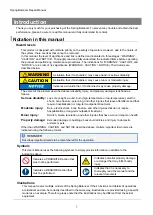
Hazard levels

This product is designed with ultimate priority on the safety of operators. However, due to the nature of
the system, there are risks that cannot be removed.
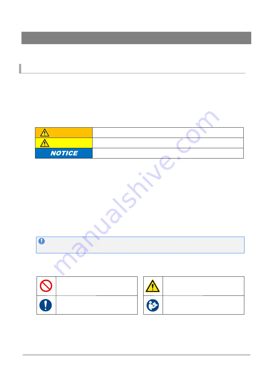
In this manual, the level of significance and risk is defined and indicated in three stages: “WARNING”,
“CAUTION”, and “NOTICE”. Thoroughly read and fully understand the indicated items before operating
the product and performing maintenance procedures. The indications for “WARNING”, “CAUTION”, and
“NOTICE” are in order of risk significance (WARNING > CAUTION > NOTICE). Their details are
described below.

WARNING
CAUTION

A situation that, if mishandled, may cause death or serious disability.

A situation that, if mishandled, may cause minor or moderate injury.

Indicates a situation that, if mishandled, may cause property damage.

The extent of the problem described above (disability, injury, and property damage) is defined as
follows.

Serious disability:

Moderate injury:

REMINDER

1

Loss of eyesight, wound, burn (high-temperature or low-temperature), electric
shock, bone fracture, poisoning, and other injuries that leave aftereffects and that
require hospitalization or long-term outpatient treatment.

Burn, electric shock, bone fracture, and other injuries that do not require
hospitalization or long-term outpatient treatment.

Scratch, bruise, laceration, and other injuries that have a minor impact on health.

Minor injury:

Property damage:

Extended damage to buildings, household articles, and injury to domestic
animals or pets.

Other than WARNING, CAUTION, and NOTICE described above, matters important to workers are
indicated using the following format.

Describes important details to be remembered for the operation.

Spring Balancer Repair Manual

Symbols

Indicates a PROHIBITED action that
must not be performed.

Illustrations

This Users Manual uses the following symbols to simply provide information in addition to the
indications above.

Indicates potential property damage
or a danger that may inflict bodily
injury.

Indicates a REQUIRED action that
must be performed.

Indicates that it is necessary to
thoroughly read the manual and the
relevant documents.

This manual covers multiple models of the Spring Balancer. If their functions and details of operations
are identical and can be correctly described in the same way, illustrations are provided taking a specific
model as an example. Therefore, please note that the illustrations may be different from the actual
equipment.

Summary of Contents for EWS-3

Page 1: ...and correct operation of the product please be sure to read this manual and fully understand its content before use After reading keep the manual safe so that you can find and use it readily In case...

Page 2: ...s 6 6 6 4 4 Applicable standards 7 Installation 8 5 1 Preparation and checks before installation 5 2 Installation procedures 5 3 Post installation checks 8 9 10 Usage 11 6 1 Pre operation inspections...

Page 3: ...Indicates a PROHIBITED action that must not be performed Illustrations 3 Spring Balancer Users Manual Loss of eyesight wound burn high temperature or low temperature electric shock bone fracture pois...

Page 4: ...y Copyright and liabilities 4 The copyright for this manual is issued to Endo Kogyo Co Ltd The manual is provided for the limited purpose of supporting the safe and proper use of the product It cannot...

Page 5: ...Management supervisor Incorrect handling of this product may cause damage to the product itself as well as a fire or injury Thoroughly read the following precautions and be sure to heed the instructi...

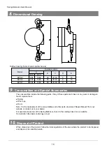
Page 6: ...6 Spring Balancer Users Manual Casing Model Factory setting load kg Stroke m Wire rope diameter mm Mass kg 4 2 Operating environment 4 3 Product specifications EWS 5 EWS 7 EWS 3 4 6 2 3 3 0 5 0 5 0 7...

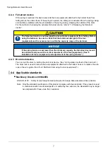
Page 7: ...f the balancer If the spring tension is set lower than the minimum capacity the fall arrest device will be activated and prevent the vertical movement of the tool equipment See 0 Installation of tools...

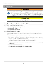
Page 8: ...eloped sufficient knowledge and operating skill for the balancer All of the following items must be prepared by the customer Auxiliary wire rope or chain Support members metal hangers Before installin...

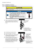
Page 9: ...lancer directly to the support member metal hanger Note The support member metal hanger and the tool equipment in the figure are indicated for reference Check that the top hook latch is closed Ensure...

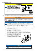
Page 10: ...also be reduced Also if the spring tension is set lower than the minimum capacity the fall arrest device will be activated and prevent the vertical movement of the tool equipment 1 2 3 Check whether t...

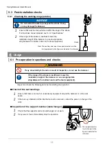
Page 11: ...ook and the tool equipment If any abnormality is found as a result of inspection do not use the balancer If the range of the stroke is insufficient lower the installation height of the balancer or use...

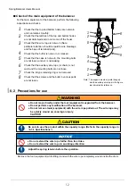
Page 12: ...not worn the mounting bolts are not loose and air is not leaking Check that the auxiliary wire rope or chain is not worn and the mounting bolts are not loose 8 Check the E type retaining ring is not r...

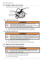
Page 13: ...ocked Do not move directly under the tool equipment suspended from the balancer Do not remove tools equipment with the wire rope pulled out The wire rope may be quickly wound up causing an injury Conf...

Page 14: ...fore checking that the drum is securely locked by moving the tool equipment up and down If the drum is locked inadequately the drum lock may be released during the work Then the wire rope may be quick...

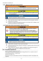
Page 15: ...pment and adjustment of the spring tension The spring tension is decreased too much and the fall arrest device has been activated Release the fall arrest device See 7 2 Releasing the fall arrest devic...

Page 16: ...llowing parts If any of these parts are broken or any wear or damage is found replace them Spring Wire rope Drum Note For the replacement of the consumables and other parts download Repair Manual from...

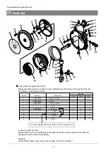
Page 17: ...7 1 1 1 1 1 1 1 1 1 How to find the parts from the list Please refer the reference number on the exploded view and choose the parts from the list according to its reference number The mark indicates t...

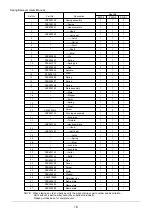
Page 18: ...EWS 5 EWS 7 1 1 1 1 1 1 1 1 1 14 14 15 16 17 18 19 20 21 22 23 P2B300089 Drum 1 1 1 1 1 1 3 1 1 1 1 P2B100110 P2B300507 LBP000750 LBP000133 KA10220512 LBP001505 Spring Plate assembly Plate Stopper Riv...

Page 19: ...14 3F TEL 052 253 6231 FAX 052 253 6240 812 0013 3 11 15 3F TEL 052 253 6231 FAX 052 253 6240 959 1261 3 14 7 TEL 0256 64 4786 FAX 0256 62 5772 E mail service endo kogyo co jp 3 14 7 Akiba cho Tsubam...

Page 20: ...correct operation of the product please be sure to read this manual and fully understand its content before use After reading keep the manual safe so that you can find and use it readily In case of re...

Page 21: ...ric shock bone fracture poisoning and other injuries that leave aftereffects and that require hospitalization or long term outpatient treatment Burn electric shock bone fracture and other injuries tha...

Page 22: ...at are not included in this product 6 Replacement of consumables 7 Usage in violation of dangers or cautions stipulated in this manual 8 Failure damage caused by any reason that is not attributable to...

Page 23: ...ting and periodic inspections The maintenance operator is required to develop sufficient knowledge and operating skill for this product The maintenance operator should read the manual thoroughly and c...

Page 24: ...tended users for this manual 1 2 3 Emergency contact in case of malfunctions 3 2 1 Daily inspections 2 2 Periodical inspections 2 3 Replacement of the wire rope 6 6 8 2 4 Replacement of the spring 9 1...

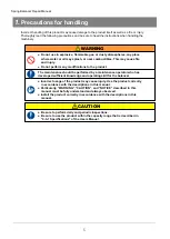
Page 25: ...or dusty atmospheres any place where water or oil may splash or near combustibles This may cause fire and injury Do not perform any modifications to the product Incorrect usage of the product may cau...

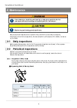
Page 26: ...replaced For details contact us or your dealer 2 1 Daily inspections Before starting the operation refer to 6 1 Pre operation inspections and checks of the separate Users Manual and perform the inspec...

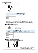
Page 27: ...aced when the dimension has reached the limiting dimension or the limiting number of broken wires within one pitch Stop using the balancer and change the wire rope see 2 3 Replacement of the wire rope...

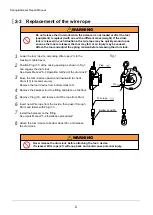
Page 28: ...rum and fasten with Plug 31 Install the balancer on the fitting See Users Manual 5 2 Installation procedures Attach the tool device to bottom Hook 23 and release the drum lock WARNING Never release th...

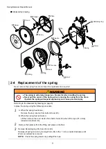
Page 29: ...center of the spring when removing the spring from the drum if pulled the spring will expand explosively and cause personal injury Referring to the disassembly drawing on page 8 replace the spring us...

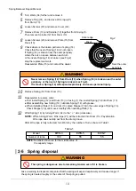
Page 30: ...e Fig 2 If removed Spring 14 will expand explosively and cause personal injury Remove Spring 14 from Drum 13 Reassemble in reverse order First install Spring 12 and Drum 13 in Casing 1 then install Sp...

Page 31: ...14 3F TEL 052 253 6231 FAX 052 253 6240 812 0013 3 11 15 3F TEL 052 253 6231 FAX 052 253 6240 959 1261 3 14 7 TEL 0256 64 4786 FAX 0256 62 5772 E mail service endo kogyo co jp 3 14 7 Akiba cho Tsubam...

Reviews: