
Installation Instructions EL-10035
PLEASE READ BEFORE USE AND RETAIN FOR FUTURE REFERENCE
WARNING:
This product contains a light source (LED) equivalent to a Class 1 Laser and care
should be taken that people do not stare into the beam.
:We recommend using a qualified electrician to install this product
:This luminaire must be installed and inspected in accordance with current IEE Wiring Regulations
and Part P of the UK Building Regulations. If in any doubt please consult a qualified
electrician.
:Use Indoors only
:
Ensure that the mains electrical supply is isolated before commencing any installation.
:This luminaire must be earthed.
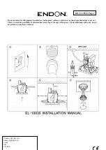
Please refer to diagrams on Page 2
Isolate at consumer unit ( fuse box ) before commencing any installation. Also switch off at wall, diagram A
1.
Cut a hole in the ceiling of the required diameter to accommodate inner ring of luminaire, ensuring there are no
joists or wires in the way and locate mains supply cables.
(Diagram B)
.
2.
This fitting can only be used where a void of at least 120mm exists between ceiling and floor above
(Diagram E)
3.
The fitting must be no less than 75 mm from any adjacent vertical surface or additional luminaire
(Diagram E)
4.
Loosen the cable restraint and open the supplied connector box
(see Diagram C)
5
Ensure that the luminaire is supported, preventing any strain being placed on the wiring.
6. Bare ends of supply wires and thread through cable restraint.
7.
Connect the supply cables to the wires of the luminaire by means of the connector block.
(See Diagram F)
Incoming Earth wire (Green, Green/Yellow or bare copper) to green /yellow wire or connector terminal
marked
Incoming live (brown or red) to brown live wire or connector terminal marked
L.
Incoming neutral (blue or black) to blue neutral wire or connector terminal marked
N
8.
Ensure that no strands of bare wire have escaped the terminals.
9. Close the connector box, and tighten cable restraint on wires.
10. Push mains cable and connection box into ceiling void.
11. Push the luminaire into the opening by squeezing together spring clips.
(See Diagram D)
Take care not to damage or trap any of the wires or leave any wires exposed.
Under no circumstances should the rear of the luminaire be covered with insulating matting or similar material.
12. Remove the lamp retaining spring clip if fitted.
13 Using Suction cup provided fit the lamp bulb of type indicated on the luminaire. Do not exceed maximum wattage
stated.
This luminaire can only be fitted with a 35W GU10 Aluminised reflector lamps.
14. Refit the lamp retaining spring by squeezing it together.
15 . Switch on the supply to the luminaire and ensure it operates correctly.
16.
If the LEDs stop working , they
cannot
be replaced.
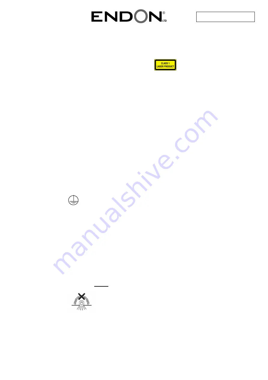
The following symbol indicates that this product must not be covered with thermally
insulating material.
Ref: F34 05v4 Page 1


