
Endon Lighting
LS9 0SE
20150903
These assembly diagrams are intended as a guide – if in doubt consult a qualified electrician.
Both
fittings follow this same general instruction.
Assembly / user instructions
N210 118
Diagram A
Diagram B
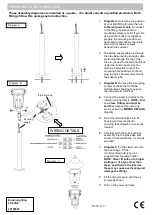
1.
Diagram A.
Determine the position
of your light fitting. Ensure there is
sufficient power cable
to connect
to the fitting. Ensure that the
mounting surface is solid. If you are
using anchor bolts (not supplied)
prepare the mounting surface as
appropriate (and ensure that there
are no other cables or pipes
beneath the surface).
2. Thread the supply cable up through
the tube base leaving enough cable
protruding through the top of the
tube to connect to the terminal block
under the lantern head. Use the
base as a template to mark the
mounting hole positions. Drill and
plug the holes and securely mount
the support tube.
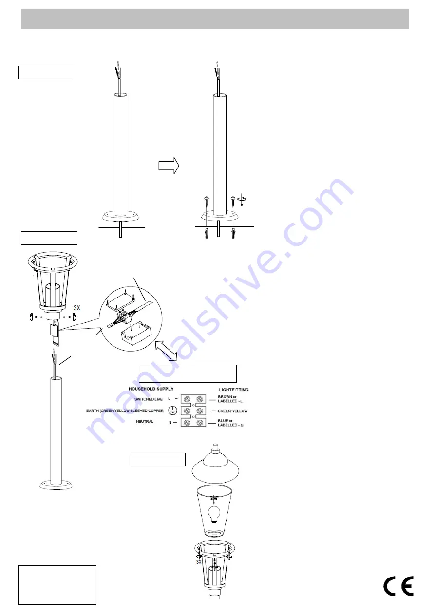
3.
Diagram B.
Remove the 4 securing
screws and take the lid off the
terminal block housing to expose
the internal terminal block.
4.
Connect the incoming mains to the
internal terminal block.
NOTE:
This
is a Class I fitting and
must be
earthed.
Connect the incoming
mains as per the
WIRING DETAILS
diagram
5.
Re-fit the terminal block into its
housing and secure the lid–
ensuring that all seals are correctly
located.
6.
Carefully push the terminal block
assembly into the tube base and
secure the head with the 3 x screws
provided.
7.
Diagram C.
Fit the clear cover into
the head cage. Fit the
recommended bulb type (not
supplied) into the lamp holder.
NOTE:
Never fit bulbs of a higher
wattage or of a type other than
those specified on the label (as
these may cause overheating and
damage the fitting).
8.
Fit the lid and secure with the 3 x
screws as shown.
9. Turn on the power and test.
WIRING DETAILS
Incoming
supply
Internal wiring
Diagram C


