Installation and commissioning
HS 55 (Batch Mode)
32
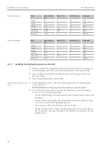
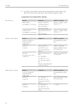
Ir coating program
Step
Temperature
[°C]
Rate [°C/s]
Hold time [s]
Purge gas
Drying
90
5
40
Max
Drying
110
1
40
Max
Drying
130
1
40
Max
Pyrolysis
1200
300
26
Stop
Atomizing
2100
500
8
Stop
Bake-out
2100
0
5
Medium
Au coating program
Step
Temperature
[°C]
Rate [°C/s]
Hold time [s]
Purge gas
Drying
80
5
25
Max
Drying
90
1
25
Max
Drying
110
5
10
Max
Pyrolysis
110
0
6
Stop
Atomizing
950
500
5
Stop
Bake-out
950
0
5
Medium
4.3.3
Installing the Hg/hydride system on the AAS
}
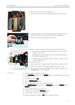
At the autosampler for the graphite tube furnace (AS-GF), loosen the clamping nut
of the hose guide, pull out the metering hose and deposit it in the waste bottle.
}
Insert the titanium cannula for the HydrEA system into the hose guide up to the
bend and secure it.
}
Place the Hg/hydride system near the AAS.
Electrical connection and inter-
faces
}
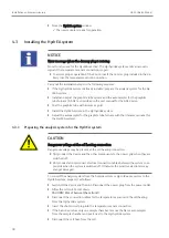
On the Hg/hydride system, connect the dummy plug to the cell unit temperature
sensor connection.
NOTICE! Without the dummy plug, the device emits a an acoustic signal.
}
Connect the functional module to the AAS: the AAS device provides the voltages
(+5 V/+24 V) for the functional module.
– Connect the "AAS" plug of the twin cable to the AS or Sampler Flame socket on the
AAS device.
– Connect the "HS" D-sub socket of the thinner cable of the twin cable to the "input
5 V/24 V" connection of the Hg/hydride system.
– The round green "AS" socket of the twin cable is not used.
– Connect the signal cable to the HS or the Hydridsystem connector of the AAS de-
vice. Connect the other end of the cable to the "AAS/RS 232" interface of the Hg/
hydride system.


