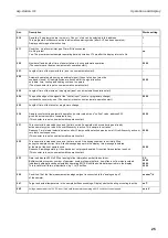
Control input
1 control input (KL8/ terminal 7 via optocoupler).
Presettable as programme change or event input.
... for programme change
Condition: Address 270 is set to "ext. signal".
A voltage of +7 to +27 Volt stops the actual programme (Adr.010) and
changes to the target programme (as preset in address 271).
0V (or open circuit) to +3 Volt returns system to the initial programme.
... as event input
Each positive signal edge initiates an immediate sample cycle. The condition
for this is that the selected active programme (as preset in address 010) is
set to "Event", (Setting up for programmes 1 to 6 is done in addresses 210,
220, 230, up to 260).
Interface (TTY
Primo-Bit)
To record sampling sequences and preset parameters.
Connect KL8/ terminal 8 (TXD) to pin 24 on the
Primo-Bit.
Connect KL8/ terminal 12 (+UTTY) to pin 17 on the
Primo-Bit.
Set up addresses 160 to 169.
Do not connect any terminals (KL...) not mentioned in these
instructions !
Connection sticker inside
terminal box lid
Attention! Details without brackets are valid for both “A2 and D2
controllers”. Details within brackets are additionally valid for the
“D2 controller”. Whether an “A2” or D2” controller is installed can be seen
on the controller legend plate.
Connection examples
Alternatives: In example "Impulse input for flow input"
a: Using external aux. voltage
b: Using internal aux. voltage
eg. for potential free contacts
b
a
KL9
KL9
asp-station d 2
Electrical intallation
11


