background image

Deltabar S

Hauser

41

Process connections FMD77 
with metallic process isolating 
diaphragms, high-pressure 
side (continued)

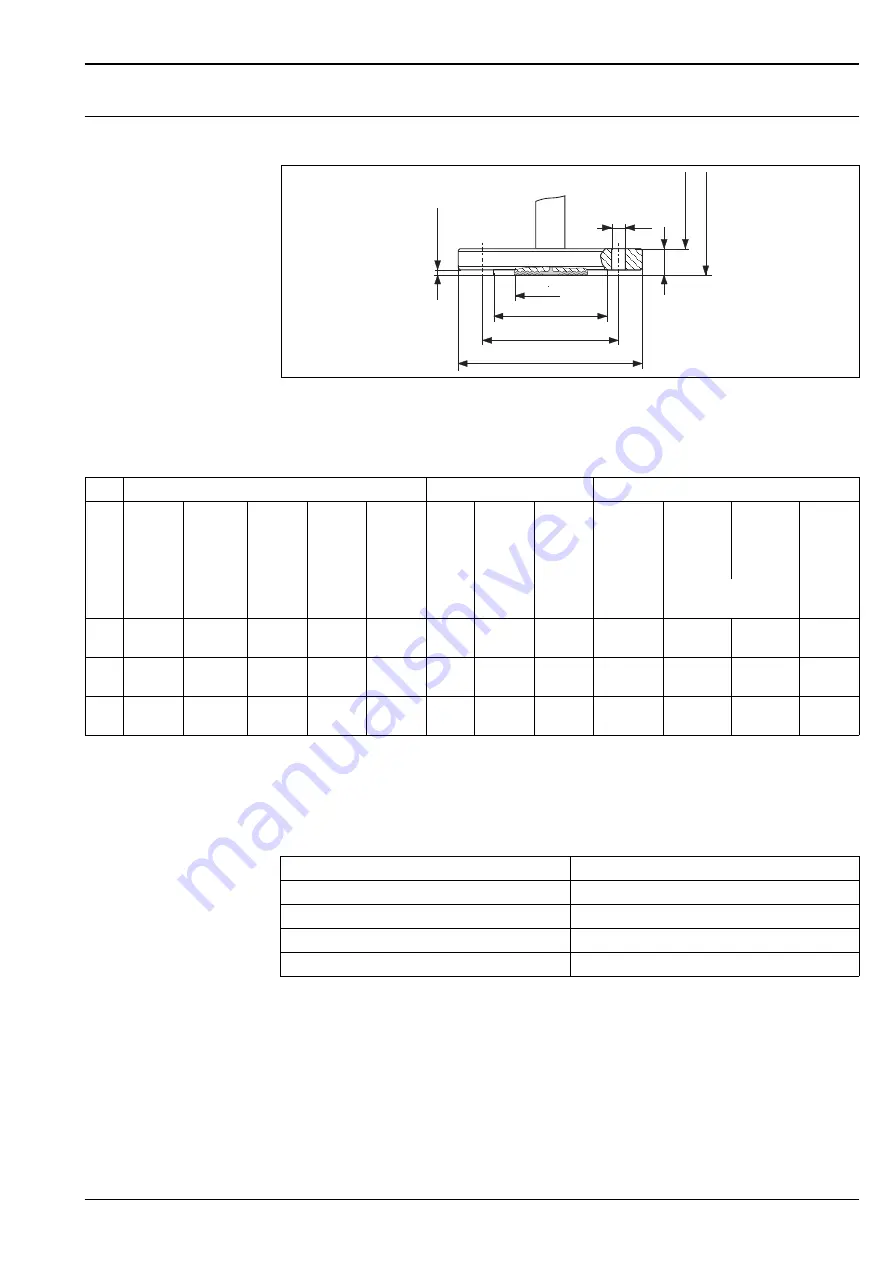
JIS flanges, connection dimensions as per JIS B 2220 BL , raised face RF

P01-FMD77xxx-06-09-xx-xx-001

Process connection FMD77, high-pressure side, JIS flange, material AISI 316L/1.4435

H

Device height 



see the following section "Device height H" 

h

Height of the device without flange thickness b

Device height H

k

D

b

H

g

h

2m

m

0.0787"

d

M

g

2

Flange 

1

Boltholes

Diaphragm seal

Ver-
sion

Nominal 
diameter

Nominal 
pressure

Diameter

Thick-
ness

Raised 
face

Quan-
tity

Diameter Hole 

circle

max. Dia-
phragm 
diameter

T

Ambient

T

Process

Flange 
weight 

2

D

b

g

g

2

k

d

M

[mm]

[in]

[mm]

[in]

[mm]

[in]

[mm]

[in]

[mm]

[in]

[mm]

[in]

[mbar/10 K]

[kg]

X

50 A

10 K

155

6.1

16

0.63

96

3.78

4

19

0.75

120

4.72

59

2.32

+3.02

+0.60

2.3

1

80 A

10 K

185

7.28

18

0.71

126

4.96

8

19

0.75

150

5.91

89

3.50

+0.23

+0.31

3.5

4

100 A

10 K

210

8.27

18

0.71

151

5.94

8

19

0.75

175

6.89

89

3.50

+0.23

+0.11

4.7

1) 

The roughness of the surface in contact with the medium, including the sealing surface of the flanges (all standards), made of Hastelloy C, Monel or 
Tantalum is Ra 0.8 

μ

m. Lower surface roughness on request.

2) Housing 

weight 

see 

ä

51

Description

Device height H (h + b)

T14 housing, optional display on the side

325 mm + flange thickness b (see tables)

T15 housing without display, flat cover

331 mm + flange thickness b (see tables)

T15 housing with display, high cover

343.5 mm + flange thickness b (see tables)

T17 housing, optional display on the side

341 mm + flange thickness b (see tables)

Summary of Contents for Deltabar S FMD 76

Page 1: ... pumps International usage thanks to a wide range of approvals Your benefits Very good reproducibility and long term stability High reference accuracy up to 0 075 as PLATINUM version 0 05 Turn down 100 1 higher on request Used for flow and differential pressure monitoring up to SIL 3 certified to IEC 61508 by TÜV SÜD HistoROM M DAT memory module Function monitored from the measuring cell to the el...

Page 2: ...conditions Installation 23 General installation instructions 23 Measuring arrangement 23 Heat insulation FMD77 24 Wall and pipe mounting 24 Separate housing version 25 Turn the housing 26 Oxygen applications 26 Ultra pure gas applications 26 Process isolating diaphragms for materials with hydrogen build up Gold Rhodium coating 27 Operating conditions Environment 27 Ambient temperature range 27 Sto...

Page 3: ...emote operation 56 Planning instructions diaphragm seal systems 58 Applications 58 Design and operation mode 58 Diaphragm seal filling oils 59 Influence of the temperature on the zero point 60 Ambient temperature range 62 Response time 62 Installation instructions 64 Certificates and approvals 66 CE mark 66 Ex approvals 66 Marine certificate 66 Functional Safety SIL IEC 61508 Declaration of confor...

Page 4: ... sides max 630 bar on one side max 100 bar on one side max 160 bar on one side max 160 bar on both sides max 240 bar Process temperature range 20 85 C 4 185 F 40 120 C 40 248 F 20 85 C 4 185 F up to 400 C 752 F up to 400 C 752 F Ambient temperature range 20 85 C 4 185 F 40 85 C 40 185 F 2 20 85 C 4 185 F 40 85 C 40 185 F 2 40 85 C 40 185 F 2 Ambient temperature range separate housing 40 to 60 C 40...

Page 5: ...ocess isolating diaphragms 3 9 are deflected on both sides by the acting pressures A filling oil 4 8 transfers the pressure to a resistance circuit bridge semi conductor technology The differential pressure dependent change of the bridge output voltage is measured and further processed Advantages Standard operating pressures 160 bar and 420 bar High long term stability Very high single sided overl...

Page 6: ...ion suppresses small flows which can lead to large fluctuations in the measured value Contains two totalizers as standard One totalizer can be reset to zero The totalizing mode and unit can be individually set for each totalizer This allows independent daily and annual quantity totalizing With the product family Deltatop Endress Hauser is offering a universal and reliable solutions for flow measur...

Page 7: ...l PROFIBUS PA The Endress Hauser devices meet the requirements as per the FISCO model Due to the low current consumption of 13 mA 1 mA up to 7 Deltabar S for Ex ia CSA IS and FM IS applications up to 27 Deltabar S for all other applications e g in non hazardous areas Ex nA etc can be operated at one bus segment with installation as per FISCO Further information on PROFIBUS PA such as requirements ...

Page 8: ...ng pressure MWP PN for the measuring device depends on the weakest element of the components selected with regard to pressure i e the process connection ä 30 ff has to be taken into consideration in addition to the measuring cell see table above Also observe pressure temperature dependency For the appropriate standards and further information see ä 29 Pressure specifications section 2 The maximum ...

Page 9: ...bar sensor Case 2 Lower range value Upper range value Example Lower range value LRV 300 mbar Upper range value URV 0 bar Nominal value URL 500 mbar Turn down TD URL LRV 1 67 1 set span URV LRV 300 mbar This span is based on the zero point P01 xMD7xxxx 05 xx xx xx 007 Example 500 mbar sensor 1 Set span 2 Zero based span 3 Nominal value i Upper range limit URL 4 Nominal measuring range 5 Sensor meas...

Page 10: ...Good Value Fail Safe Value factory setting Wrong Value Load 4 20 mA HART P01 xMD7xxxx 05 xx xx xx 000 Load diagram observe the position of the jumper and the explosion protection ä 17 section Taking 4 20 mA test signal 1 Jumper for 4 20 mA test signal inserted in Non test position 2 Jumper for 4 20 mA test signal inserted in Test position 3 Supply voltage 10 5 11 5 30 V DC for 1 2 D 1 GD 1 2 GD FM...

Page 11: ... Dead time t1 Time constant T63 t2 PMD75 45 ms 10 mbar and 30 mbar measuring cell 200 ms 100 mbar measuring cell 60 ms 500 mbar measuring cell 45 ms 3 bar measuring cell 40 ms 16 bar and 40 bar measuring cell 60 ms FMD77 FMD78 dependent on the diaphragm seal PMD70 FMD76 90 ms 25 mbar measuring cell 4700 ms 100 mbar measuring cell 280 ms 500 mbar measuring cell 210 ms 3 bar measuring cell 110 ms Ty...

Page 12: ...sed control loop acyclic 10 s Response time cyclic 80 ms acyclic 40 ms All values are typical values Cycle time Update time 250 ms Type Dead time t1 Time constant T63 t2 PMD75 295 ms 10 mbar and 30 mbar measuring cell 200 ms 100 mbar measuring cell 60 ms 500 mbar measuring cell 45 ms 3 bar measuring cell 40 ms 16 bar and 40 bar measuring cell 60 ms FMD77 FMD78 dependent on the diaphragm seal PMD70...

Page 13: ...c Device selectable yes Default Basic Devce Number VCRs 44 Number of Link Objects in VFD 50 Permanent Entries 44 Client VCRs 0 Server VCRs 5 Source VCRs 8 Sink VCRs 0 Subscriber VCRs 12 Publisher VCRs 19 Slot time 4 Min Inter PDU delay 12 Max response delay 10 Block Content Output values TRD1 Block contains all parameters related to the measurement Pressure Flow or Level Channel 1 Process temperat...

Page 14: ...le use of popular measurement math functions The user does not have to know how to write equations The math algorithm is selected by name chosen by the user for the function to be done 50 ms standard Input Selector Block The input selector block provides selection of up to four inputs and generates an output based on the configured action This block normally recei ves its inputs from AI blocks The...

Page 15: ...jumper is inserted in accordance with the illustration 7 minimum supply voltage 11 5 V DC jumper is inserted in Test position 8 Devices with integrated overvoltage protection are labelled OVP overvoltage protection here ä 28 PROFIBUS PA The digital communication signal is transmitted to the bus via a 2 wire connection The bus also provides the auxiliary energy For further information on the networ...

Page 16: ...8 2 MBP Devices with Harting plug Han7D P01 xMD7xxxx 04 xx xx xx 000 Left electrical connection for devices with Harting plug Han7D Right view of the plug connector at the device Devices with M12 plug P01 xMD7xxxx 04 xx xx xx 008 Left electrical connection for devices with M12 plug Right view of the plug at the device Endress Hauser offers for devices with M12 plug the following accessories Plug i...

Page 17: ...the jumper As a result operation is also possible with lower voltage sources Observe the position of the jumper in accordance with the following table 7 8 Approval Typ Clamping range Standard II1 2G Exia IS Plastic M20x1 5 5 10 mm ATEX II1 2D II1 3D II1 2GD Exia II1GD Exia II3G Ex nA Metal M20x1 5 Ex e 7 10 5 mm Jumper position for test signal Description Taking 4 20 mA test signal via plus and te...

Page 18: ...rsion for non hazardous areas jumper for 4 20 mA test signal in Non test position 10 5 45 V DC PROFIBUS PA Version for non hazardous areas 9 32 V DC FOUNDATION Fieldbus Version for non hazardous areas 9 32 V DC Current consumption PROFIBUS PA 13 mA 1 mA switch on current corresponds to IEC 61158 2 Clause 21 FOUNDATION Fieldbus 15 mA 1 mA switch on current corresponds to IEC 61158 2 Clause 21 Cable...

Page 19: ...ty Influence of the installation position PMD70 FMD76 3 mbar 1 3 PMD75 4 mbar 1 3 FMD77 32 mbar 2 3 Note Position dependent zero shift can be corrected ä 23 section General installation instructions and ä 62 ff section Response time Vibration effects 1 year 5 years 10 year Measuring range mbar of URL 10 0 150 100 0 180 500 0 025 0 050 0 075 3000 0 038 0 075 0 150 16000 0 025 0 110 0 210 1 Device i...

Page 20: ...formance Measuring cell of the set span 10 mbar 30 mbar TD 1 1 TD 1 1 0 15 0 15 x TD 100 mbar TD 1 1 to TD 4 1 TD 4 1 0 075 0 012 x TD 0 027 500 mbar TD 1 1 to TD 15 1 TD 15 1 0 075 0 0015 x TD 0 053 Platinum version 00 mbar TD 1 1 0 05 Measuring cell FMD77 FMD78 of the set span influence of the diaphragm seal included 100 mbar TD 1 1 to TD 4 1 TD 4 1 0 15 0 03 x TD 0 03 TD 1 1 to TD 4 1 TD 4 1 0 ...

Page 21: ... bar 0 70 of URL 70 bar 0 70 of URL 70 bar 100 mbar 0 15 of URL 70 bar 0 14 of URL 70 bar 0 42 of URL 70 bar 0 42 of URL 70 bar 500 mbar 0 075 of URL 70 bar 0 14 of URL 70 bar 0 14 of URL 70 bar 0 14 of URL 70 bar 3 bar 0 075 of URL 70 bar 0 14 of URL 70 bar 0 14 of URL 70 bar 0 14 of URL 70 bar 16 bar 0 075 of URL 70 bar 0 14 of URL 70 bar 0 14 of URL 70 bar 0 14 of URL 70 bar 40 bar 0 075 of URL...

Page 22: ...nce of the operating pressure on zero point and span PMD70 FMD76 Note The influence of the operating pressure on the zero point can be calibrated out Thermal change of the zero output and the output span PMD70 FMD76 Measuring cell of the set span 25 mbar TD 1 1 TD 1 1 0 15 0 15 x TD 100 mbar TD 1 1 to TD 4 1 TD 4 1 0 075 0 012 x TD 0 027 500 mbar 3 bar TD 1 1 to TD 15 1 TD 15 1 0 075 0 0015 x TD 0...

Page 23: ...t suited to flow measurement Measuring arrangement for gases Mount device above the measuring point Measuring arrangement for liquids and vapours Mount device below tapping point For flow measurement in vapours mount the condensate traps at the same level as the same the tapping point and at the same distance from Deltabar S Level measurement PMD70 PMD75 FMD76 and FMD77 are best suited to level me...

Page 24: ...0 Maximum permitted insulation height Wall and pipe mounting Endress Hauser offers a mounting bracket for installing the device on pipes or walls ä 67 ff feature 110 Additional options 2 Note If a valve block is used its dimensions should also be taken into consideration P01 xMD7xxxx 11 xx xx xx 008 Mounting bracket for wall and pipe mounting A bracket including mounting accessories for pipe mount...

Page 25: ... and cable ready mounted The housing and a mounting bracket are enclosed as separate units The cable is provided with a socket at both ends These sockets are simply connected to the housing and the sensor 1 Process connection with sensor 2 Cable both ends are fitted with a socket 3 Mounting bracket provided suitable for pipe and wall mounting 4 Housing with electronic insert Degree of protection f...

Page 26: ... for gaseous oxygen applications are listed in the following table with the specification pmax Ultra pure gas applications Endress Hauser also offers devices for special applications such as ultra pure gas cleaned from oil and grease No special restrictions regarding the process conditions apply to these devices ä 67 ff PMD70 and PMD75 feature 80 Seal FMD76 and FMD77 feature 70 Process connection ...

Page 27: ...rmal change may be exceeded See also DIN 16086 Storage temperature range 40 90 C 40 194 F On site display 40 85 C 40 185 F Separate housing 40 to 60 C 40 to 140 F Degree of protection ä 67 ff feature 30 Housing Cable entry Protection Degree of protection IP 68 for T17 housing 1 83 mH2O for 24 h Seperate housing ä 25 Climate class Class 4K4H air temperature 20 55 C 4 131F relative humidity 4 100 fu...

Page 28: ... the following section Process temperature range seals FMD77 and FMD78 Observe the temperature application limits of the diaphragm seal oil ä 59 sections Diaphragm seal filling oils FMD77 and FMD78 Do not use diaphragm seals with 0 09 mm PTFE foil on AISI 316L 1 4435 1 4405 for vacuum applications upper temperature limit 204 C 400 F Process temperature range seals PMD70 with ceramic process isolat...

Page 29: ... In the case of sensor range and process connections where the OPL Over Pressure Limit of the pressure connection is smaller than the nominal value of the sensor the device is set at the factory at the very maximum to the OPL value of the process connection If you want to use the entire sensor range select a process connection with a higher OPL value 1 5 x PN PN MWP In oxygen applications the valu...

Page 30: ...sions T15 optional display on the top P01 xMD7xxxx 06 00 xx xx 001 Front view left hand side view top view See the process connection in question for installation height Housing weight see ä 51 Housing dimensions T17 optional display on the top P01 xMD7xxxx 06 00 xx xx 002 Front view left hand side view top view See the process connection in question for installation height Housing weight see ä 51...

Page 31: ...8 NPT H Ver sion Connection Mounting Material Accessories Weight 1 1 Process connection weight for housing weight see ä 51 B 1 4 18 NPT IEC 61518 7 16 20 UNF Steel C 22 8 2 vent valves AISI 316L 1 4404 included 4 0 kg D 1 4 18 NPT IEC 61518 7 16 20 UNF AISI 316L 2 2 AISI 316L 1 4435 4 0 kg F 1 4 18 NPT IEC 61518 7 16 20 UNF Alloy C276 3 3 Alloy C276 2 4819 Vent valves Alloy C276 2 4819 see ä 68 fe...

Page 32: ...ction Device height H Device height H 41 3 54 84 96 PVDF 108 7 16 20 UNF 1 4 18 NPT H Version Connection Mounting Material Weight 1 1 Process connection weight for housing weight see ä 51 G 1 4 18 NPT IEC 61518 7 16 20 UNF PVDF 3 8 kg Description Device height H T14 housing optional display on the side 253 mm T15 housing without display flat cover 259 mm T15 housing with display high cover 271 5 m...

Page 33: ... Ver sion Connection Mounting Material Accessories Weight 1 1 Weight of process connections without vent valves with 10 mbar or 30 mbar sensors process connections without vent valves with sensors 100 mbar weght approx 800 g less Housing weight see ä 51 B 1 4 18 NPT IEC 61518 7 16 20 UNF Steel C 22 8 2 vent valves AISI 316L 1 4404 included 4 2 kg D 1 4 18 NPT IEC 61518 7 16 20 UNF AISI 316L 2 2 AI...

Page 34: ...g Material Accessories Weight 1 1 Weight of process connections without vent valves with 10 mbar or 30 mbar sensors process connections without vent valves with sensors 100 mbar weght approx 800 g less Housing weight see ä 51 C 1 4 18 NPT IEC 61518 7 16 20 UNF Steel C 22 8 4 locking screws and 2 vent valves included AISI 316L 1 4404 4 2 kg E 1 4 18 NPT IEC 61518 7 16 20 UNF AISI 316L 2 2 PN 160 ba...

Page 35: ...ice height see the following section Device height H 1 Diaphragm seal attachment 2 Copper ring seal 3 Process isolating diaphragm Device height H H 7 16 20 UNF M6 72 41 3 98 54 54 87 Description Device height H 1 1 Values for devices with 10 mbar and 30 mbar measuring cell in brackets T14 housing optional display on the side 217 mm 230 mm T15 housing without display flat cover 223 mm 236 mm T15 ho...

Page 36: ...ht of the device without flange thickness b 41 3 41 k g b H 2 ø46 g2 D h 7 16 20 UNF 1 4 18 NPT Flange 1 Boltholes Version Material Nominal diameter Shape 2 Nominal pressure Diameter Thickness Raised face Quantity Diameter Hole circle Flange weight 3 D b g g2 k mm mm mm mm mm kg B AISI 316L DN 80 B1 D PN 10 40 200 24 138 8 18 160 5 3 D ECTFE 4 DN 80 PN 10 40 200 24 8 18 160 5 3 E Alloy C276 5 DN 8...

Page 37: ... in mm in mm in mm in mm kg ANSI flanges P AISI 316 316L 3 3 in 150 lb sq in 7 5 190 5 0 94 23 9 5 127 4 0 75 19 1 6 152 4 4 9 R ECTFE 4 4 9 S Alloy C276 5 5 T AISI 316 316L 4 in 150 lb sq in 9 228 5 0 94 23 9 6 19 157 2 8 0 75 19 1 7 5 190 5 7 1 U ECTFE 7 1 V Alloy C276 8 W AISI 316 316L 4 in 300 lb sq in 10 254 1 25 31 8 6 19 157 2 8 0 88 22 4 7 88 200 2 11 7 JIS flanges 1 AISI 316L 80 A 10 K 7 ...

Page 38: ... flanges material of the basic device AISI 316L 1 4435 or 1 4404 high pressure side see the following section Process connections high pressure side FMD77 Description Device height H h b T14 housing optional display on the side 175 mm flange thickness b see tables T15 housing without display flat cover 181 mm flange thickness b see tables T15 housing with display high cover 193 5 mm flange thickne...

Page 39: ...connection FMD77 high pressure side EN DIN flange with and without extended diaphragm seal material AISI 316L H Device height see ä 41 section Device height H h Height of the device without flange thickness b L g k D b H g h 1 6 mm 0 06 in d3 dM g2 Flange 1 Boltholes Diaphragm seal Ver sion No minal dia meter Nominal pressure Shape 2 Dia meter Thick ness Raised face Exten sion length Exten sion di...

Page 40: ... Hole circle max Dia phragm dia meter TK Am bient TK Pro cess Flange weight 2 D b g L d3 g2 k dM lb sq in in mm in mm in mm in mm in mm in mm in mm in mm mbar 10 K kg N 2 150 6 152 4 0 75 19 1 3 62 91 9 4 0 75 19 1 4 75 120 7 2 32 59 3 02 0 90 2 6 P 3 150 7 5 190 5 0 94 23 9 5 127 4 0 75 19 1 6 152 4 3 50 89 0 23 0 18 5 1 Q 3 150 7 5 190 5 0 94 23 9 5 127 2 50 8 3 76 2 4 0 75 19 1 6 152 4 2 83 72 ...

Page 41: ... b g g2 k dM mm in mm in mm in mm in mm in mm in mbar 10 K kg X 50 A 10 K 155 6 1 16 0 63 96 3 78 4 19 0 75 120 4 72 59 2 32 3 02 0 60 2 3 1 80 A 10 K 185 7 28 18 0 71 126 4 96 8 19 0 75 150 5 91 89 3 50 0 23 0 31 3 5 4 100 A 10 K 210 8 27 18 0 71 151 5 94 8 19 0 75 175 6 89 89 3 50 0 23 0 11 4 7 1 The roughness of the surface in contact with the medium including the sealing surface of the flanges...

Page 42: ... height the following section Device height H 1 Diaphragm seal attachment Device height H Description Device height T14 housing optional display on the side 217 mm T15 housing without display flat cover 223 mm T15 housing with display high cover 235 5 mm T17 housing optional display on the side 233 mm ...

Page 43: ...n other words the dimensions of a diaphragm seal supplied can deviate from the dimensions given in this document Diaphragm seal cell structure P01 FMD78xxx 06 09 xx xx 000 Process connection FMD78 material AISI 316L D b dM Flange Diaphragm seal Version Nominal diameter Nominal pressure 1 max Diameter Thickness max Diaphragm diameter TK Process Weight of two diaphragm seals D b dM mm mm mm mbar 10K...

Page 44: ...n FMD78 Material AISI 316L surface roughness of the wetted surfaces 0 8 m as standard Lower surface roughness on request 6 90 G 100 SW22 22 AF 1 2 NPT 89 100 SW22 22 AF Version Material Nominal pressure TK Process Weight of two diaphragm seals mbar 10 K kg GA AISI 316L PN 40 0 75 2 9 RL AISI 316L PN 40 0 55 2 9 dM C7 h Version Nominal diameter ISO 2852 Nominal diameter DIN 32676 Nominal diameter D...

Page 45: ...he wetted surfaces 0 8 m as standard Lower surface roughness on request h d 2 L D Version Nominal diameter ISO 2852 Nominal diameter Diameter Diameter Diameter Height Face to face length TK Process Weight of two diaphragm seals D d1 d2 h L in mm mm mm mm mm mbar 10 K kg SB DN 25 1 22 5 43 5 50 5 67 126 4 49 3 4 SC 1 DN 38 1 1 2 35 5 43 5 50 5 67 126 3 46 2 SD 1 DN 51 2 48 6 56 5 64 79 100 2 69 3 4...

Page 46: ...ection sanitary tank spud extended diaphragm seal 2 P01 FMD78xxx 06 09 xx xx 011 Process connection FMD78 surface roughness of the wetted surfaces 0 8 m as standard Lower surface roughness on request 4 x ø11 5 ø65 1 2 ø84 ø105 d 50 M max 23 6 41 Version Material Nominal pressure TK Process Weight of two diaphragm seals mbar 10 K kg TK AISI 316L PN 25 1 25 1 5 53 5 ø91 45 ø100 ø132 7 Version Materi...

Page 47: ...f k m dM Taper adapter Slotted nut Diaphragm seal Ver sion Nominal diameter Nominal pressure Diameter Adapter height Thread Height Height max Diaphragm diameter TK Process Weight of two diaphragm seals D f G k m dM mm mm mm mm mm mbar 10 K kg MR DN 50 PN 25 68 5 11 Rd 78 x 1 6 22 19 52 0 90 2 2 MS DN 65 PN 25 86 12 Rd 95 x 1 6 25 21 66 0 29 4 0 MT DN 80 PN 25 100 12 Rd 110 x 1 4 30 26 81 0 30 5 1 ...

Page 48: ...C 220 20 8 18 180 89 0 35 9 5 B6 DN 100 PN 25 40 B1 D 235 24 162 8 22 190 89 0 19 13 3 1 The roughness of the surface in contact with the medium including the sealing surface of the flanges all standards made of Hastelloy C Monel or Tantalum is Ra 0 8 μm Lower surface roughness on request 2 Designation as per DIN 2527 in brackets JIS flange 1 Boltholes Diaphragm seal Ver sion Nominal diameter Nomi...

Page 49: ...19 1 3 62 91 9 4 0 75 19 1 4 75 120 7 2 32 59 1 10 5 2 AR 2 300 6 5 165 1 0 88 22 5 3 62 91 9 8 0 75 19 1 5 127 2 32 59 0 75 6 8 AG 3 150 7 5 190 5 0 94 23 9 5 127 4 0 75 19 1 6 152 4 3 50 89 0 40 10 2 AS 3 300 8 25 209 5 1 12 28 4 5 127 8 0 88 22 4 6 62 168 1 3 50 89 0 35 14 J4 3 150 7 5 190 5 0 94 23 9 5 127 2 50 8 3 76 4 0 75 19 1 6 152 4 2 83 72 0 29 12 4 101 6 13 2 6 152 4 14 2 8 203 6 15 4 A...

Page 50: ... xx xx 002 Reduction of the mounting height of the process connection for application of the separate housing 1 Process connection adapter If the separate housing is used the mounting height of the process connection is reduced by approx 45 mm as compared to the dimensions of the standard version The minimum bending radius r for the cable is 120 mm 4 7 45 5 ø51 7 101 84 131 118 45 5 ø51 7 101 76 1...

Page 51: ...lass Silicone VMQ Nameplates AISI 304 1 4301 T17 housing Housing Stainless steel AISI 316L 1 4404 Sight glass Version for non hazardous area ATEX Ex ia NEPSI Zone 0 1 Ex ia IECEx Zone 0 1 Ex ia FM NI FM IS CSA IS Polycarbonate PC ATEX 1 2 D ATEX 1 3 D ATEX 1 GD ATEX 1 2 GD ATEX 3 G FM DIP CSA Dust Ex Mineral glass Cable gland Polyamid PA for Dust Ex CuZn nickel plated Blind plug PBT GF30 FR for Du...

Page 52: ...measuring cell Mineral oil for oxygen and ultra pure gas applications Inert oil Voltalef 1A Measuring cell PMD75 FMD77 and FMD78 filling oil Silicone oil for oxygen and ultra pure gas applications Inert oil Halocarbon 6 3 Process isolating diaphragm material PMD70 FMD76 Al2O3 Aluminium oxide ceramic PMD75 FMD77 FMD78 AISI 316L 1 4435 Alloy C276 2 4819 Monel 400 2 4360 Tantal AISI 316L 1 4435 with ...

Page 53: ...for PROFIBUS PA as graphical display of the scaled value of the AI Block Simple and complete menu guidance thanks to seperation of the parameters into three levels Ech parameter is given as 3 digit ID number for easy navigation Option for configuring the display according to individual requirements and desires such as language alternating display display of other measured values such as sensor tem...

Page 54: ...isplay 3 Slot for optional HistoROM M DAT 4 DIP switch for locking unlocking measured value relevant parameters 5 DIP switch for damping on off 6 Green LED to indicate value being accepted P01 xxxxxxxx 19 xx xx xx 105 Elektronikeinsatz PROFIBUS PA 1 Green LED to indicate value being accepted 2 Key for position calibration and device reset 3 DIP switch for bus address 4 Slot for optional display 5 ...

Page 55: ...dbus Remote operation via Handheld terminal Field Communicator 375 see Chapter Hard und Software for on site and remote operation ä 56 ff Use an FF configuration program for e g NI FBUS configurator to connect devices with FOUNDATION Fieldbus signal into an FF network set FF specific parameter Operation with NI FBUS Configurator The NI FBUS Configurator is an easy to use graphical environment for ...

Page 56: ... details refer to TI404F 00 en Commubox FXA291 The Commubox FXA291 connects Endress Hauser field instruent with CDI interface Endress Hauser Common Data Interface to the USB interface of a personal computer or a notebook For details refer to TI405C 07 en Note For the following Endress Hauser instruments you need the ToF Adapter FXA291 as an additional accessory Cerabar S PMC71 PMP7x Deltabar S PMD...

Page 57: ...d in the scope of delivery You can copy data from one transmitter to another transmitter when operating a FOUNDATION Fieldbus device via an FF configuration program You need the Endress Hauser FieldCare operating program and the Commubox FXA291 service interface and the ToF Adapter FXA291 to be able to access the data and events saved in the HistoROM M DAT FieldCare FieldCare is an Endress Hauser ...

Page 58: ...smitter Endress Hauser delivers all diaphragm seal systems as welded versions The system is hermetically sealed which ensures the highest reliability Note The correlations between the individual diaphragm seal components are presented in the following section For further information and comprehensive diaphragm seal system designs please contact your local Endress Hauser Sales Center Diaphragm seal...

Page 59: ...ume of its side flange and as a result of its volume change The volume change is the volume that has to be shifted to pass through the complete measuring range Differential pressure transmitters from Endress Hauser are optimised with regard to minimum volume change and side flange Diaphragm seal filling oils Version 1 Filling oil Permissible temperature range at 0 05 bar pabs 1 bar Permissible tem...

Page 60: ...fficients obtained from the diagrams apply to silicone oil and the process isolating diaphragm material AISI 316L 1 4435 For other filling oils these temperature coefficients must be multiplied by the TK correction factor of the corresponding filling oil For the TK correction factors see ä 59 section Diaphragm seal filling oils P01 FMD78xxx 05 xx xx en 004 Example for Diaphragm seal versions B5 EN...

Page 61: ...0 K RF AISI 316L KH JIS flange 100 A 10 K RF AISI 316L MT DIN 11851 DN 80 PN 25 AISI 316L M5 DIN 11851 DN 80 PN 25 socket AISI 316L 3 MS DIN 11851 DN 65 PN 25 AISI 316L M4 DIN 11851 DN 65 PN 25 socket AISI 316L J4 ANSI flange 3 150 lbs RF AISI 316 316L Extensions 2 4 6 8 4 SC Pipe seal diaphragm Tri Clamp ISO 2852 DN 38 1 1 2 AISI 316L 1 4435 SD Pipe seal diaphragm Tri Clamp ISO 2852 DN 51 2 AISI ...

Page 62: ...ogy solutions that are close to the application limits Response time The viscosity of the filling oil the capillary length and the capillary internal diameter influence the frictional resistance The greater the frictional resistance the longer the response time Furthermore the volume change of the measuring cell influences the response time The lower the volume change of the measuring cell is the ...

Page 63: ...erature oil Vegetable oil Inert oil Nominal diameter Capillary internal diameter Measuring cell Response time T90 sec m Ambient temperature range 20 C 90 100 t T90 Minimise response time by Comments Larger capillary internal diameter The temperature effect increases with increasing diameter Shorter capillaries Filling oil with lower viscosity Observe compatibility of the filling oil with the proce...

Page 64: ... the following example For devices with capillary a suitable fastening device mounting bracket is recommended When using a mounting bracket sufficient strain relief must be allowed for in order to prevent the capillary bending down bending radius 100 mm The temperature and length of both capillaries should be the same when using two sided diaphragm seal systems Selecting the measuring cell observe...

Page 65: ...the left must not be exceeded The maximum height difference is dependent on the density of the filling oil and the smallest ever pressure that is permitted to occur at the diaphragm seal on the positive side empty tank see the following illustration on the right Result If the tank were full a differential pressure of 51 80 mbar would be present at the differential pressure transmitter When the tan...

Page 66: ... see ä 67 ff Feature 100 Additional option 1 and Feature 110 Additional option 2 version E SIL IEC 61508 declaration of Conformity Overspill protection WHG German Water Resources Act See Ordering information ä 67 see also ZE259P 00 de CRN approvals Some device versions have CRN approval For a CRN approved device a CRN approved process connection ä 68 feature 70 Process connection has to be ordered...

Page 67: ...EMA 4X 6P M12x1 PA plug E Aluminium T14 housing optional display on the side IP 66 67 NEMA 4X 6P 7 8 FF plug F Aluminium T14 housing optional display on the side IP 65 NEMA 4X Han7D plug 90 J Aluminium T15 housing optional display on the top IP 66 67 NEMA 4X 6P Gland M 20x1 5 K Aluminium T15 housing optional display on the top IP 66 67 NEMA 4X 6P Thread G 1 2 L Aluminium T15 housing optional displ...

Page 68: ...ration of conformity B Material test certificate for wetted components inspection certificate as per EN 10204 3 1 acc to specification 52005759 M Overvoltage protection J Software adjustment see additional spec N HistoROM M DAT S GL ABS marine certificate U Mounting bracket wall pipe 304 V Mounting on shut off valve from above W Mounting on shut off valve from below 2 Test report acc to EN10204 2 ...

Page 69: ...Deltabar S Endress Hauser 69 PMD70 continued 995 Identification Z1 Measuring point TAG Z2 Bus address PMD70 order code ...

Page 70: ...tection A Aluminium T14 housing optional display on the side IP 66 67 NEMA 4X 6P Gland M 20x1 5 B Aluminium T14 housing optional display on the side IP 66 67 NEMA 4X 6P Thread G 1 2 C Aluminium T14 housing optional display on the side IP 66 67 NEMA 4X 6P Thread 1 2 NPT D Aluminium T14 housing optional display on the side IP 66 67 NEMA 4X 6P M12x1 PA plug E Aluminium T14 housing optional display on...

Page 71: ...diaphragm material 1 AISI 316L 2 Alloy C 3 Monel 5 Tantal 6 Alloy C with Gold Rhodium coating 70 Process connection Material B 1 4 18 NPT IEC 61518 mounting 7 16 20 UNF C22 8 CRN including 2 vent valves AISI 316L C 1 4 18 NPT IEC 61518 mounting 7 16 20 UNF C22 8 side vent including 4 fastening bolt connections and 2 vent valves AISI 316L D 1 4 18 NPT IEC 61518 mounting 7 16 20 UNF AISI 316L CRN in...

Page 72: ...ficate inspection certificate as per EN 10204 3 1 110 Additional option 2 A not selected E SIL IEC 61508 Declaration of conformity B Material test certificate for wetted components inspection certificate as per EN 10204 3 1 acc to specification 52005759 G Separate housing cable length see additional spec mounting bracket wall pipe 316L FM CSA IS nur für Div 1 Installation K Vent valves 2 pieces Al...

Page 73: ...lug E Aluminium T14 housing optional display on the side IP 66 67 NEMA 4X 6P 7 8 FF plug F Aluminium T14 housing optional display on the side IP 65 NEMA 4X Han7D plug 90 J Aluminium T15 housing optional display on the top IP 66 67 NEMA 4X 6P Gland M 20x1 5 K Aluminium T15 housing optional display on the top IP 66 67 NEMA 4X 6P Thread G 1 2 L Aluminium T15 housing optional display on the top IP 66 ...

Page 74: ...az CRN Q 1 4 18 NPT IEC 61518 Alloy C Chemraz CRN S 1 4 18 NPT IEC 61518 AISI 316L FKM Viton cleaned from oil and greace CRN T 1 4 18 NPT IEC 61518 AISI 316L FKM Viton cleaned for oxygen service CRN U RC 1 4 AISI 316L FKM Viton CRN 80 Process connection high pressure side Material EN DIN flanges B DN 80 PN 10 40 B1 AISI 316L D DN 80 PN 10 40 AISI 316L with ECTFE coating Safety instructions observe...

Page 75: ... selected E SIL IEC 61508 Declaration of conformity G Separate housing cable length see additional spec mounting bracket wall pipe 316L FM CSA IS nur für Div 1 Installation K Vent valves 2 pieces Alloy C M Overvoltage protection J Software adjustment see additional spec N HistoROM M DAT R Screws 7 16 UNF length 1 1 2 4 pieces for oval flange adapter PZO S GL ABS marine certificate U Mounting brack...

Page 76: ...otection A Aluminium T14 housing optional display on the side IP 66 67 NEMA 4X 6P Gland M 20x1 5 B Aluminium T14 housing optional display on the side IP 66 67 NEMA 4X 6P Thread G 1 2 C Aluminium T14 housing optional display on the side IP 66 67 NEMA 4X 6P Thread 1 2 NPT D Aluminium T14 housing optional display on the side IP 66 67 NEMA 4X 6P M12x1 PA plug E Aluminium T14 housing optional display o...

Page 77: ... 4 18 NPT IEC 61518 Alloy C PTFE C4 ring CRN K 1 4 18 NPT IEC 61518 AISI 316L EPDM CRN L 1 4 18 NPT IEC 61518 Alloy C EPDM CRN M 1 4 18 NPT IEC 61518 AISI 316L Kalrez CRN N 1 4 18 NPT IEC 61518 Alloy C Kalrez CRN P 1 4 18 NPT IEC 61518 AISI 316L Chemraz CRN Q 1 4 18 NPT IEC 61518 Alloy C Chemraz CRN S 1 4 18 NPT IEC 61518 AISI 316L cleaned from oil and greace CRN T 1 4 18 NPT IEC 61518 AISI 316L c...

Page 78: ...t acc to EN 10204 2 2 3 Routine test with certificate inspection certificate as per EN 10204 3 1 4 Overpressure test with certificate inspection certificate as per EN 10204 3 1 110 Additional options 2 A Additional options 2 not selected E SIL IEC 61508 declaration of conformity G Separate housing cable length see additional spec mounting bracket wall pipe 316L FM CSA IS nur für Div 1 Installation...

Page 79: ...otection A Aluminium T14 housing optional display on the side IP 66 67 NEMA 4X 6P Gland M 20x1 5 B Aluminium T14 housing optional display on the side IP 66 67 NEMA 4X 6P Thread G 1 2 C Aluminium T14 housing optional display on the side IP 66 67 NEMA 4X 6P Thread 1 2 NPT D Aluminium T14 housing optional display on the side IP 66 67 NEMA 4X 6P M12x1 PA plug E Aluminium T14 housing optional display o...

Page 80: ...VH Cell 3 150 2500 lbs AISI 316L CRN VJ Cell 4 150 2500 lbs AISI 316L CRN Threaded connections GA Thread ISO 228 G 1 2 B PN 40 AISI 316L separator PTFE seal RL Thread ANSI 1 2 MNPT PN 40 AISI 316L separator PTFE seal Clamp connections TB Tri Clamp ISO 2852 DN 25 1 DIN 32676 DN 25 EHEDG 3A AISI 316L TC Tri Clamp ISO 2852 DN 25 DN 38 1 1 1 2 EHEDG 3A AISI 316L TD Tri Clamp ISO 2852 DN 40 DN 51 2 DN ...

Page 81: ...nents inspection certificate as per EN 10204 acc to specification 52005759 C NACE MR0175 material D Material test certificate for wetted components as per EN 10204 3 1 and NACE MR0175 material inspection certificate as per EN 10204 acc to specification 52010806 M Overvoltage protection J Software adjustment see additional spec N HistoROM module S GL ABS marine certificate U Mounting bracket wall p...

Page 82: ...Deltabar S 4 20 mA SD189P 00 en Safety Instructions Certificate Type of Protection Device Electronic insert Documentation Version in the order code ATEX II 1 2 G Ex ia IIC T6 WHG PMD70 PMD75 FMD76 FMD77 FMD78 4 20 mA HART PROFIBUS PA FOUNDATION Fieldbus XA235P 1 6 ATEX II 1 2 D PMD70 PMD75 FMD77 FMD78 4 20 mA HART PROFIBUS PA FOUNDATION Fieldbus XA237P XA280P 2 ATEX II 1 2 D Ex ia IIC T6 FMD76 4 2...

Page 83: ...ldbus XC004P H NEPSI Ex d IIC T6 PMD75 FMD77 FMD78 4 20 mA HART PROFIBUS PA FOUNDATION Fieldbus XC006P G Certificate Type of Protection Device Electronic insert Documentation Version in the order code Certificate Type of Protection Device Electronic insert Documentation Version in the order code FM IS Class I II III Division 1 Groups A G NI Class I Division 2 Groups A D AEx ia PMD70 PMD75 FMD76 FM...

Page 84: ...MD75 FMD77 FMD78 4 20 mA HART PROFIBUS PA FOUNDATION Fieldbus XA242P ZD153P ZD186P XA242P ZD190P ZD191P F CSA XP Cl I Div 1 Gr B D Ex d Zone 1 2 PMD75 FMD77 FMD78 4 20 mA HART PROFIBUS PA FOUNDATION Fieldbus ZD229P V Instruments International Endress Hauser Instruments International AG Kaegenstrasse 2 4153 Reinach Switzerland Tel 41 61 715 81 00 Fax 41 61 715 25 00 www endress com info ii endress ...

Reviews: