Electrical connection
Ecograph T, RSG35
20
Hauser
Meaning of the LEDs
Beneath the Ethernet connection (see rear of device) there are two light emitting diodes
which indicate the status of the Ethernet interface.
• Yellow LED: link signal; is lit when the device is connected to a network. If this LED is not
illuminated then communication is impossible.
• Green LED: Tx/Rx; flashes irregularly if the device is transmitting or receiving data.
6.3.10 Option: Ethernet Modbus TCP slave
The Modbus TCP interface is used to connect to higher-ranking SCADA systems (Modbus
master) to transmit all measured values and process values. Up to 12 analog inputs and 6
digital inputs can be transmitted via Modbus and stored in the device. Form a physical
point of view, the Modbus TCP interface is identical to the Ethernet interface.
6.3.11 Option: Modbus RTU slave
The Modbus RTU (RS485) interface is galvanically isolated (testing voltage: 500 V) and is
used to connect to higher-ranking systems to transmit all measured values and process
values. Up to 12 analog inputs and 6 digital inputs can be transmitted via Modbus and
stored in the device. Connection is via the combined RS232/RS485 interface.
Modbus TCP and Modbus RTU cannot be used at the same time.
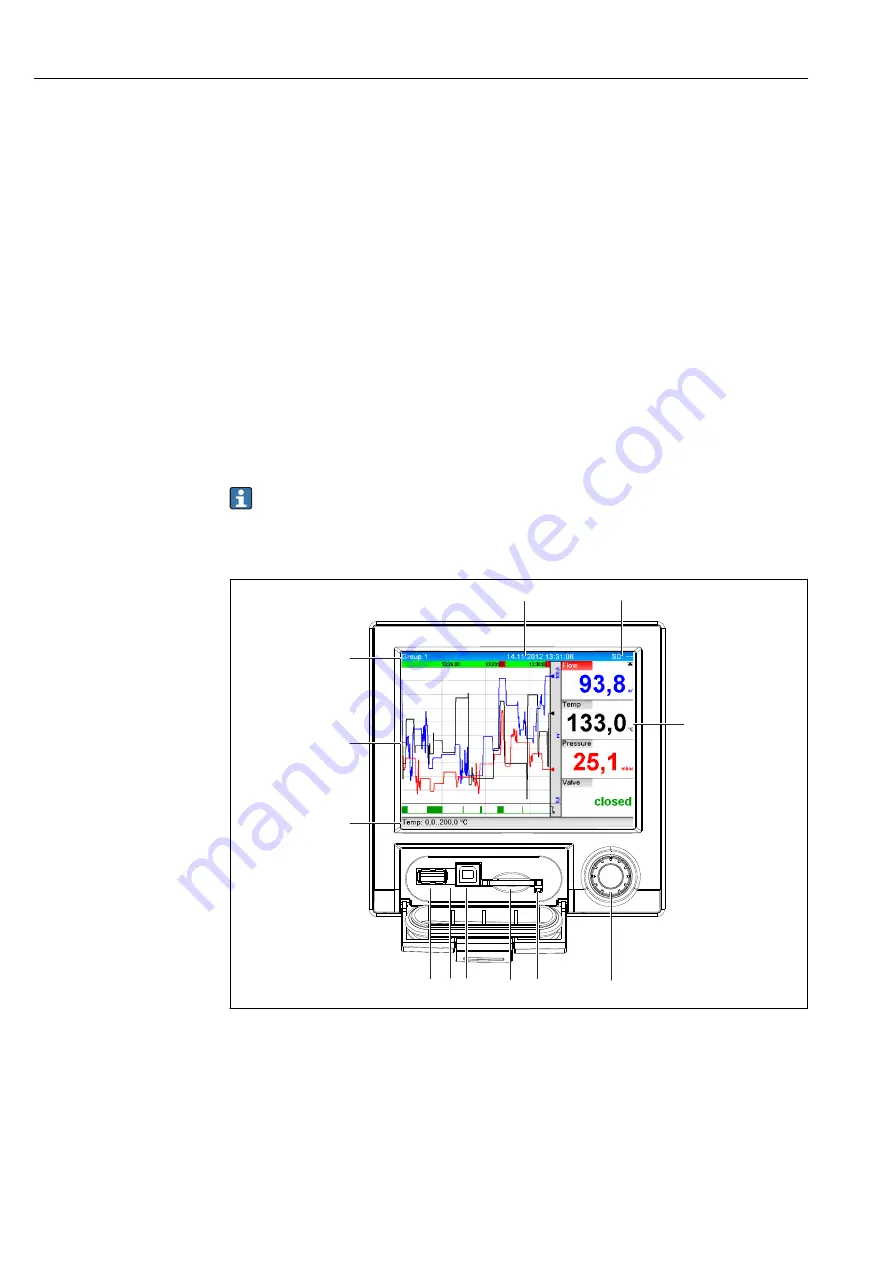
6.3.12 Connections at front of device
6
4
3
2
1
5
7
8
9
10
11
12
A0019501
6
Front of device with open flap
1
Navigator
2
LED at SD slot. Orange LED lights up or flashes when the device writes to or reads from the SD card.
3
Slot for SD card
4
USB B socket "Function" e.g. to connect to PC or laptop
5
Green LED lit: power supply present
6
USB A socket "Host" e.g. for USB memory stick or external keyboard
7-12 For a description of the displays, see the "Operability" section


