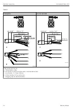


Electrical connection
Flowmeter Proline 500
34
Hauser
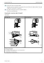
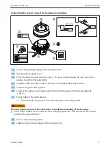
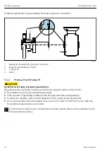
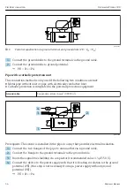
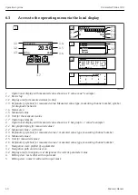
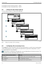
Potential equalization via grounding electrodes on process connection
2
1
3
4
A0028972
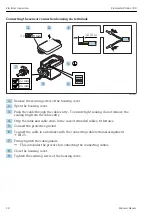
1
Hexagonal-headed bolts of process connection
2
Integrated grounding electrodes
3
O-ring seal
4
Sensor
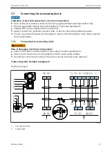
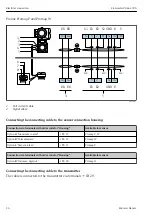
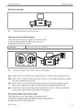
5.4.2
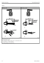
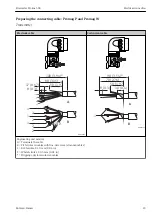
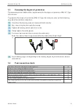
Promag P and Promag W
L
CAUTION
Insufficient or faulty potential equalization.
May destroy the electrodes and thus result in the complete failure of the device!
‣
Pay attention to in-house grounding concepts
‣
Take account of operating conditions like the pipe material and grounding
‣
Connect the medium, sensor and transmitter to the same electrical potential
‣
Use a ground cable with a minimum cross-section of 6 mm
2
(0.0093 in
2
) and a cable lug
for potential equalization connections
For devices intended for use in hazardous locations, please observe the guidelines in the
Ex documentation (XA).
Summary of Contents for Flowmeter Proline 500
Page 47: ......


